...
| Date | Location | Identified issue | Resolution |
|---|---|---|---|
| Oct 20, 2017 | PCB: Motherboard rev 1.0 | Steve Sommers - Capacitor C188 designation is duplicated. C186 is missing. 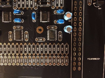 | From Roman:
|
| Oct 21, 2017 | PCB: Voice card Rev 1.0 | Resistors R40, R45, R151 and R146 have space on the circuit boards, but there is nothing specified in the BOM | These are not used and were left in place for possible filter modifications. Leave the components spaces empty (do not put anything there). |
| Nov 11, 2017 | PSU Board Rev 1.0 | DACs not initializing on some boards. Note: Updated in BOM 1.0.8 | PSU Board Changes per Roman: Change C12 to 1uf 6.3V or higher Change C13 - 330uf 6.3V or higher 8MM DIA /3.5 LS C13 increased delays the boot of +3.3v digital rail, c12 reduced makes 5v analog rail boot faster, Without change sometimes they don’t start, since digital 3.3v comes to DAC before 5v |
| Dec 23, 2017 | All boards | Roman suggests that both power consumption, and heat reduction can be obtained by substituting all TL072/TL074 OPAmps with the lower current TL062/TL064. Roman also states that the pre-built units contained the TL062/TL064s | This was first suggested as a substitution for the voice cards only with TL072/TL074s being used on all other boards. However, Roman has since updated the BOM to use TL062/TL064s throughout. (REV1.0.9) |
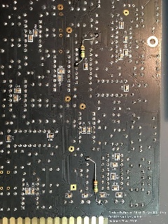
Jan 15, 2018 | All Voiceboards | waveform glitch not the same like CS-80 | To apply the "glitch fix", you will need to solder two 1.0 Meg resistors per voice board, one for each oscillator. They can be easily added to the back side of the circuit board, so all existing components can remain unchanged. click to enlarge |
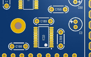
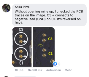
| 2.October 2020 | DIY version rev.1 only Breakoutboard PCB | Capacitor C3 - the polarity is wrong labeled on the PCB this affects the 5.2V power rail for the fan and USB. | remove the capacitor and install them with swapped polarity. you can use a new capacitor 100uF 15uF 10V/16V RM2mm max.5mm diameter (as before) ignore the schematics - there's a 100uF shown - but the BOM shows an 15uF capacitor thanks to all involved people to report this bug. 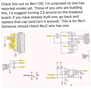
|
...