...
| Date | Location | Identified issue | Resolution |
|---|---|---|---|
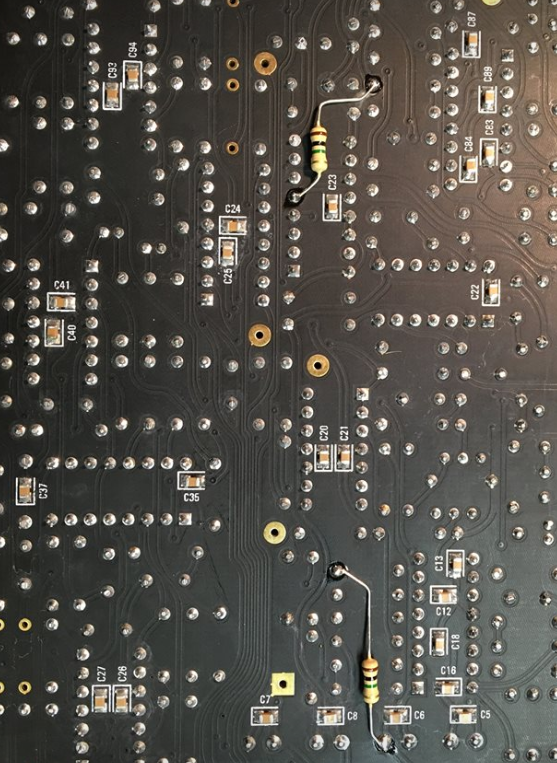
| Oct 20, 2017 | PCB: Motherboard rev 1.0 | Steve Sommers - Capacitor C188 designation is duplicated. C186 is missing. 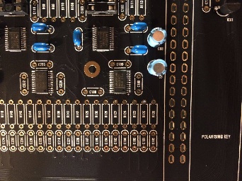 | From Roman:
|
| Oct 21, 2017 | PCB: Voice card Rev 1.0 | Resistors R40, R45, R151 and R146 have space on the circuit boards, but there is nothing specified in the BOM | These are not used and were left in place for possible filter modifications. Leave the components spaces empty (do not put anything there). |
| Nov 11, 2017 | PSU Board Rev 1.0 | DACs not initializing on some boards. Note: Updated in BOM 1.0.8 | PSU Board Changes per Roman: Change C12 to 1uf 6.3V or higher Change C13 - 330uf 6.3V or higher 8MM DIA /3.5 LS C13 increased delays the boot of +3.3v digital rail, c12 reduced makes 5v analog rail boot faster, Without change sometimes they don’t start, since digital 3.3v comes to DAC before 5v |
| Dec 23, 2017 | All boards | Roman suggests that both power consumption, and heat reduction can be obtained by substituting all TL072/TL074 OPAmps with the lower current TL062/TL064. Roman also states that the pre-built units contained the TL062/TL064s | This was first suggested as a substitution for the voice cards only with TL072/TL074s being used on all other boards. However, Roman has since updated the BOM to use TL062/TL064s throughout. (REV1.0.9) |
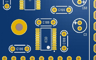
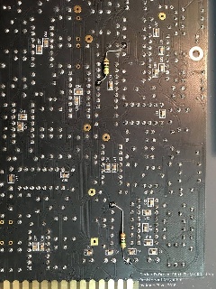
Jan 15, 2018 | All Voiceboards | waveform glitch not the same like CS-80 | To apply the "glitch fix", you will need to solder two 1.0 Meg resistors per voice board, one for each oscillator. They can be easily added to the back side of the circuit board, so all existing components can remain unchanged. click to enlarge |
Bugtracker
further bugs, issues, problems are reported here (here are user reported issues due to soldering failures or other issues reported too)
...
make sure your OLED folow this pinout VCC-GND-SCL-SDA, very often shows the shop the correct pinout but deliver another type.
AND short the pins on the display side (where the Frontpanel is) to prevent shorts to the Frontpanel.
| Panel | ||
|---|---|---|
| ||
REV1.1.0 CORRECTED THE AMOUNT OF DIP16 SOCKETS REV1.0.9 TL074 CHANGED TO TL064, TL072 CHANGED TO TL062. HEAT SINK, THERMAL PAD, COOLING FAN AND MOUNTING HARDWARE ARE OPTIONAL IF TL06X OPAMPS ARE USED. VOLUME KNOB AND SLIDER CAPS PART# CHANGED. REV1.0.8 CHANGED C12 TO 1uF, C13 TO 330uF ON THE PSU BOARD REV1.0.7 CHANGED R2 ON THE OUTPUT BOARD TO 22R, CHANGED C6 ON THE MOTHERBOARD TO 10uF REV1.0.6 CHANGED 1N5817 TO BAT85S ON THE MOTHERBOARD REV1.0.5 ADDED USB A TO USB B ADAPTER REV1.0.4 CORRECTED 30K MOUSER PART # IN A VOICE CARD REV1.0.3 CHANGED HEAT SINK QUANTITY, C2 ON OUTPUT BOARD IS 100uF NOW REV1.0.2: ADDED ST LINK PROGRAMMER |
...
| Warning |
|---|
some users reported that the board doesn´t fit in the case - the mainboard pcb is too big.. on the mainboard is on top and bottom a small 3-4mm pcb stripe, that need´s to be removed. |
| Tip |
|---|
when you have trouble with your voicecards like a whistle on upper or lower card or wrong VCF... the calibration process is not perfect, swap this "faulty" voicecard with another card and run the calibration for the single voicem not for all. if everything wents wrong: insert only one voicecard in Slot1, run calibration (not the tune function). when everything is fine, add the second card to slot 2 and run again calibration - on slot 2, insert card 3 and so on.. |
Build Tips
prepare BOM and Parts:
modify the BOM, change it to single sheets (tabs) instead in one list or you can easily scroll in the long list to the wrong board (like motherboard instead control board)
when you have received the parts, prepare different boxes (resistors, capacitors, ICs, hardware)
sort the bags to values like 1R-9,99K 1K-9.99K 10K-100K and so on.. same for capacitors.
start on the boards with the most used values like 499R
this speed up your build
measure one part from each bag and label the bag like "T" for tested.
check the BOM for the quantity for the board and count each value, drop it in a small box or put the secure on your desk before you install.
Troubleshooting
a lot of users reported problems with slider calibration or display failures, auto tune.
the most issues are from a faulty ARM chip, this can easily happen by:
wrong component values on motherboard and Controlboard, shorted 3.3V power.
a short connection from 3.3V to ground or (12V/5V/-12V) is enough to kill a function in your ARM Chip.
Q: what can you do in case of failure ??
A: read and understand the schematics and double check the BOM against your parts (there are few different values between BOM and Schematic) the latest BOM (see above) is correct not the schematics !
| Panel | ||
|---|---|---|
| ||
some users plugged the powersupply in a voicecard slot and earn a damaged ARM processor. to minimize this risk, few solutions: put a tape on the voicecard slots 2-8 or use a cable tie to shorten/bind the powercable between powersupply and breakoutboard as short as possible (you can´t attach the powersupply furthermore in a voicecard slot) |
| Tip | ||
|---|---|---|
when you have trouble with your voicecards like a whistle on upper or lower card or wrong VCF... the calibration process is not perfect, swap this "faulty" voicecard with another card and run the calibration for the single voicecard not for all. if everything wents wrong: insert only one voicecard in Slot1, run calibration (not the tune function). when everything is fine, add the second card to slot 2 and run again calibration - on slot 2, insert card 3 and so on.. | ||
| Panel | ||
| ||
some users plugged the powersupply in a voicecard slot and earn a damaged ARM processor. to minimize this risk, few solutions: put a tape on the voicecard slots 2-8 or use a cable tie to shorten/bind the powercable between powersupply and breakoutboard as short as possible (you can´t attach the powersupply furthermore in a voicecard slot) |
Firmware:
check the download location: http://www.deckardsdream.com/downloads/ for updates, i prefer to wait few weeks before you install a newer version, or check the closed facebook group for comments.
...
http://www.deckardsdream.com/downloads/DD-FIRMWARE-REV1.2.8.bin (latest)
Firmware 1.29: here (latest)
Menu Structure:
DD-MENU-STRUCTURE-REV1.0 (1).pdf
...
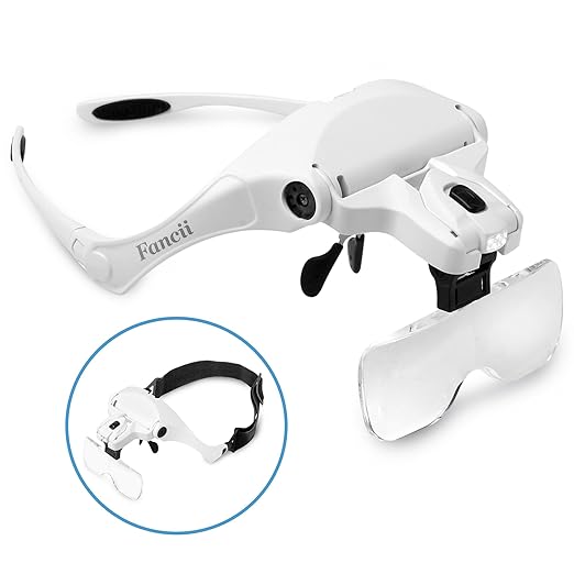
a very helpful Tool for the SMD Soldering: (and sponsoring for this website hosting)
(link here )
Wooden Case: Ross Lammond (UK) http://www.lamonddesign.co.uk/index/ → not anymore available, if you want one, contact me