| Panel | ||||||||||
|---|---|---|---|---|---|---|---|---|---|---|
| ||||||||||
Projecttitel: Arp1601 CloneStatus:
Startdate: end of 2014Duedate: Summer 2015last update: January 2017 |
1601 rev.3 update: (Summer 2016 jhulk's pcb run)
C42 = 1nF c0g Capacitor
C5 = 33nF or use 39nF Filmcap or ceramic cap
Muffwiggler Thread:
https://www.muffwiggler.com/forum/viewtopic.php?t=110640
Muffwiggler Build Thread
https://www.muffwiggler.com/forum/viewtopic.php?t=138862
| Attachments | ||
|---|---|---|
|
| Gallery | ||||
|---|---|---|---|---|
|
BOM: (BOM update 12 jun.2015)
please see attachment list above
the file: ARP1601_PartList_ sorted is sorted for resistor and capacitor values -please use this for building ARP 1601 Parts List_sorted.xls
for Kipplings groupbuy round2 you need a 12uH Inductor and 47uF/25V cap too (this parts are not in the BOM)
Mouser part nr.: 652-RLB9012-120KL and 1-off 667-EEU-EB1E470SH
for Round 1 BOM: dont buy the expensive ferrit bead on mouser.. this part dont fit.
please use: 2x 875-28L0138-80R-10
keycapps: 3 needed - if you buy the keycap kit, it includes 14caps (instead of 13)
Builders Guide: (left rev.1 - right rev.2)
|
|
PCB Designator/Component Numbers
ARP 1601 Sequencer Rev 4 - PCB (full).pdf
Known Issues: (rev1. and rev2)
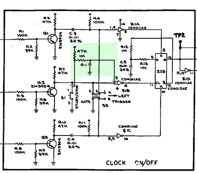
The start/stop pushbutton is a little prone to contact bounce giving multiple triggers. The ever-helpful Nordcore has a fix involving changing one IC, two additional resistors and one capacitor and one track to cut with a little point to point wiring. Unfortunately it is too late to incorporate these changes into the round 2 PCBs so they will remain as PCB rev 2. A quick fix kippling have tried with good success is increasing C5 to 33nF, and adding a 1nF capacitor soldered directly across the SW1 terminals, and for me at least gives no noticeable lag.
Further tips will be added as I think of them or they are pointed out by users
Mods for Start/Stop: As mentioned above change C5 (10nF) to something around 33/39nF, and add a 1nF directly across the pins of SW1 to eliminate the contact bounce causing the unreliable start/stop push-button operation.
take a look at Page 9 of the Buiders Guide rev.2 (for Rev.1 Users are this fix too)
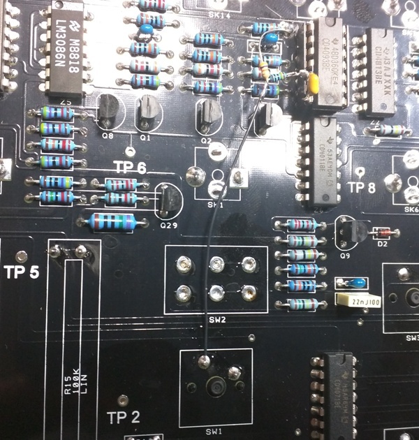
further its possible to change the IC "Z1" CD 4011 to CD4093 for the start/stop issue, cut on frontpanel pcb side a trace add few R/Cs (1M and 10nF ?) - see this pics:
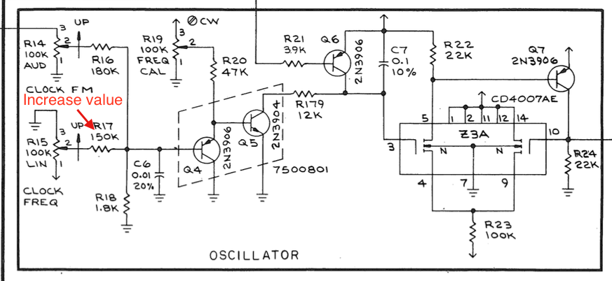
Mod: Clock Frequency (thanks to Ultravox)
source: https://www.muffwiggler.com/forum/viewtopic.php?t=138862&postdays=0&postorder=desc&start=25
I was able to get the Clock Freq slider to work full travel by increasing the resistance of R17 to approx 222.5k. I didn't have a resistor of that value so I put a 100k trimmer in series with R17 and adjusted it so that the clock will still operate when the slider is set to min. The Clock Freq slider now gives 1Hz - 100Hz from min to max travel. 
Schematics (round 1)
ARP 1601 Sequencer - Schematic (round 1).pdf
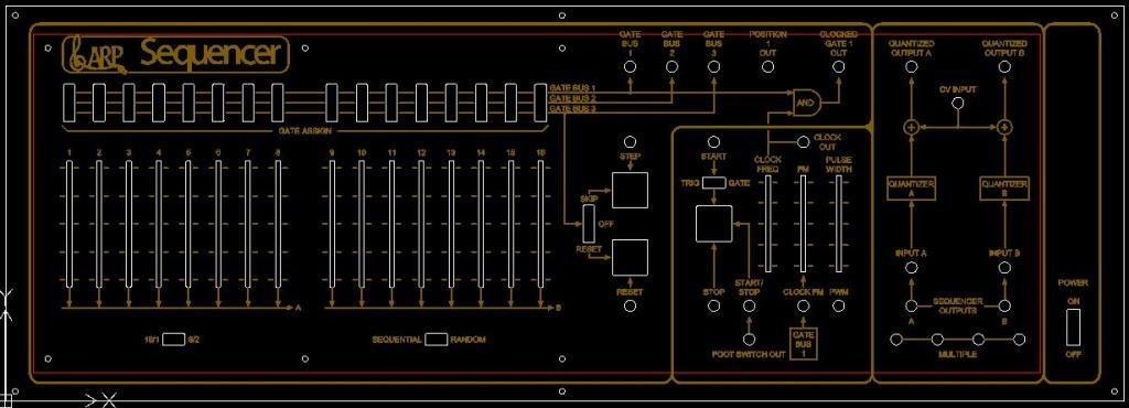
Panel:
|