...
2.solder as shown in my pictures some headers for midiimplant on the gatebooster pcb, i prefer a adapter with male/female headers to remove the midi pcb from gatebooster (for repairs or testing)
3. do start the wiring job task for the midi connector - mount it in the case - then solder the cables (or you run later in trouble when you try to build in the midi connector in the case - the connector must be built in from front.)
...
| Info |
|---|
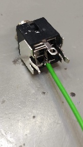
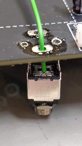
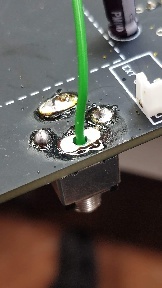
the KBD Out jack switch pin must be isolated from the pcb trace: (TTSH REV 2-3-4) 2 options are possible: (ON REV1 is no Switch pin connected on the PCB, you can connect the switch pin directly there, on the pcb) the KBD CV JACK: connect a cable to switch pin, without making a connection to the KBD Cv out PCB pin: |
5. connect 3 cables to the GATE/S-H section (AR/ADSR)
...