| Panel | ||||||||||
|---|---|---|---|---|---|---|---|---|---|---|
| ||||||||||
Projecttitel: ISE-NINStatus:
Startdate: 26th Aug.2022Duedate: 15th Sep.2022Last page update:1724Nov.Nov.2022Manufacture link: https://black-corporation.comModwiggler: https://www.modwiggler.com/forum/viewtopic.php?t=265268Facebook Build Group: https://www.facebook.com/groups/517757979447099Facebook User Group: https://www.facebook.com/groups/800008500661600 |
...
| Panel | ||||
|---|---|---|---|---|
| ||||
Before you built the ISE-NIN kit:
|
...
BOM:
ISE-NIN-BOM-REV1.0.2.xlsx uploaded 24.Nov.2022
ISE-NIN-BOM-REV1.0.1.xlsx updated by BC on 24th.Sep.2022
ISE-NIN-BOM-REV1.0.1.pdf. updated by BC on 24th.Sep.2022
Add to your order: ATS-55250W-C1-R0 (from the) its a 1inch cooler for DC-DC PSU (read the issue list) 17.Nov.2022
the Mouser project can't be shared anymore, its the best that everyone create a own to their requirements.
...
use eBay or tme for the SMT caps to safe money
Tempco resistors and matched pair transistor are available by me:
https://www.diysynth.de/diy-components/passive-komponenten/tempco/tempco.html
...
The case and panel are included with the kit.
"The additional parts include:
ENCLOSURE PANELEnclosure and Frontpanel
19" Rack Ears x2
Display Lens x1 (in the blac Noise IC Box)
...
| Issue ID | Date | Location | Type | Identified issue | Resolution | related for development | affected PCB version | fixed Version |
|---|---|---|---|---|---|---|---|---|
| 1 |
|
| -- | BOM 1.02 | ||||
| 2 | 30. Aug 2022 | BOM - Mainboard | INFO | the 220uF caps on the Mainboard are BI-POLAR - | respect the BOM partnumber | |||
| 3 | 07 Sep. 2022 | Hardware Board | BUG | there's no Pinout described on the Hardware Board for the OLED - | please read the INFO section in the next table on "OLED selection" carefully | can be improved with better silkscreen information | 1.0 | |
| 4 | 13 Sep. 2022 | BOM: Voices | INFO | the Mouser BOM shows 32x 240pF C0G capacitors for the Voices - used in the OTA Filter. These are 10% tolerance. | you can change the capacitors to Polypropylene, Silver MICA, Styrene - with 1-2.5% or match good capacitors in this range with an LCR meter (check the data sheets of the meter) | - | - | - |
| 5 | 13.Sep.2022 | create a Silkscreen for MTA156 Powerheader pinout | 1.0 | |||||
| 6 | 29.Oct.2022 | Voices | BUG | Sync doesn't work correct | remove on every Voicecard IC3 (TL064). bend Pin 12 of the TL064 outwards, install the IC3 back in the IC socket and solder a resistor leg from Pin12 to Pin10 as shown: 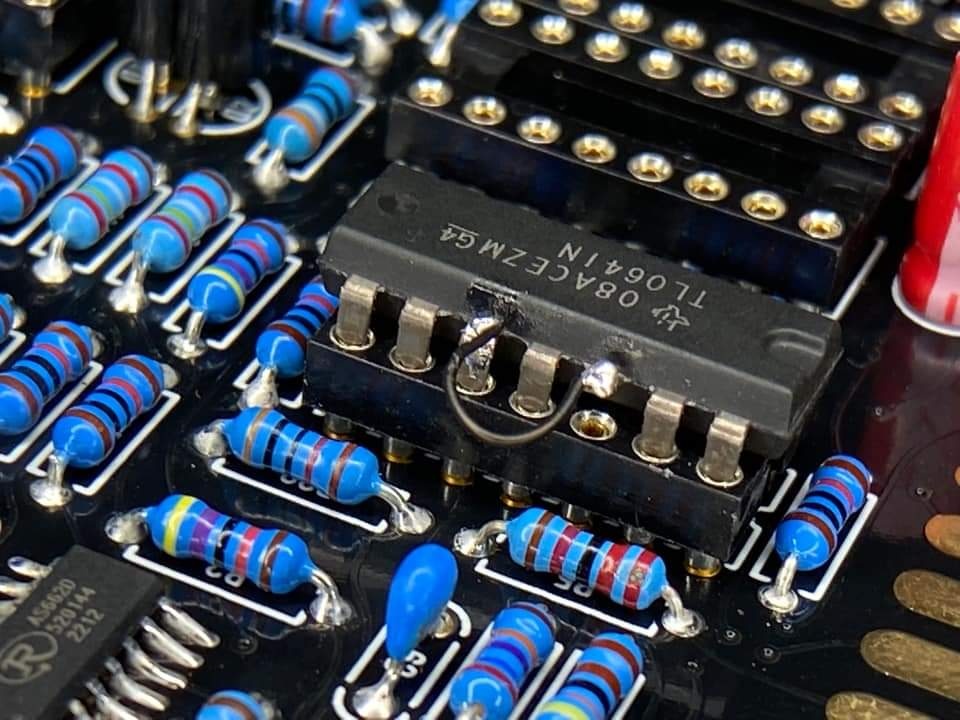 | fix the PCB routing | 1.0 | |
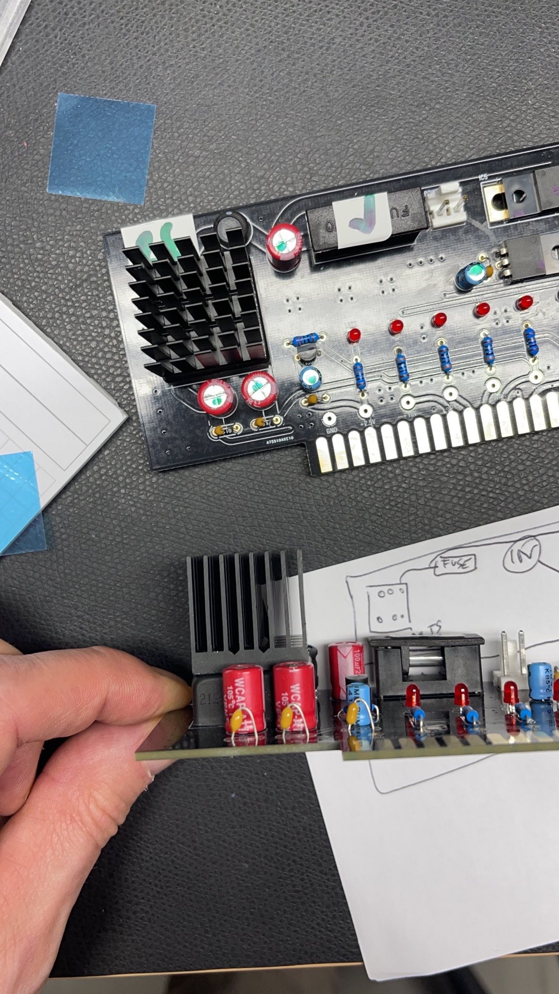
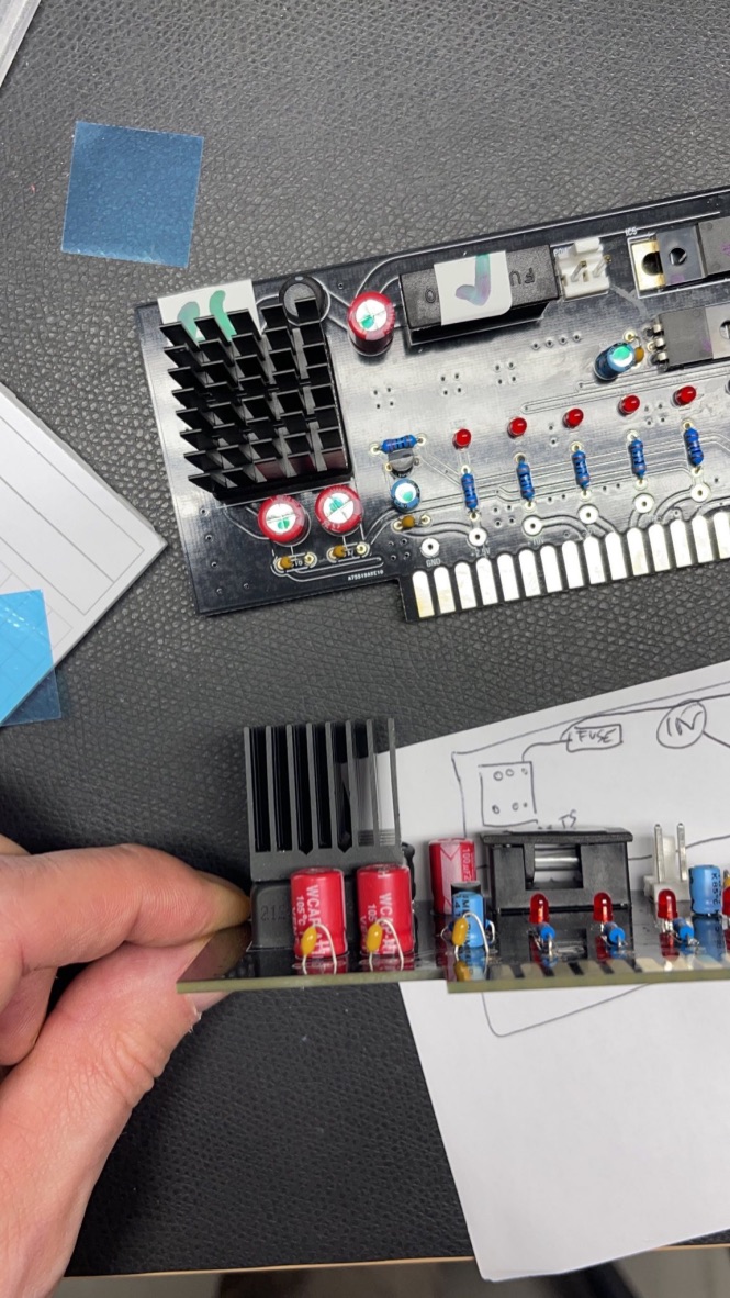
| 7 | 17.Nov.2022 | PSU card | INFO | The DC-DC converter goes very hot after 30minutes, but its within the data sheet specs (65degrees Celsius is the max. operation). The 65 degrees can be reached in Summer or other conditions (few hours operating time) But for longterm stability of the components, I highly recommend the usage of a big cooler | install a 25x25mm cooler with an high of minimum 20mm. I found on tme.eu a product with self adhesive foil and 24.5mm height. the temperature of the DC.DC converter is 51 degrees after an hour on the regulator and 43 degrees on the cooler. TME Part nr. ATS-55250W-C1-R0 |
| 1.0 | BOM 1.02 is updated for this !! |
Important Information before you start assembling:
...
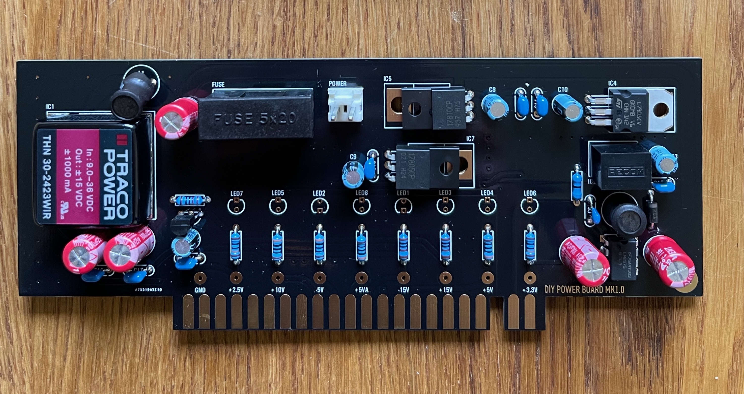
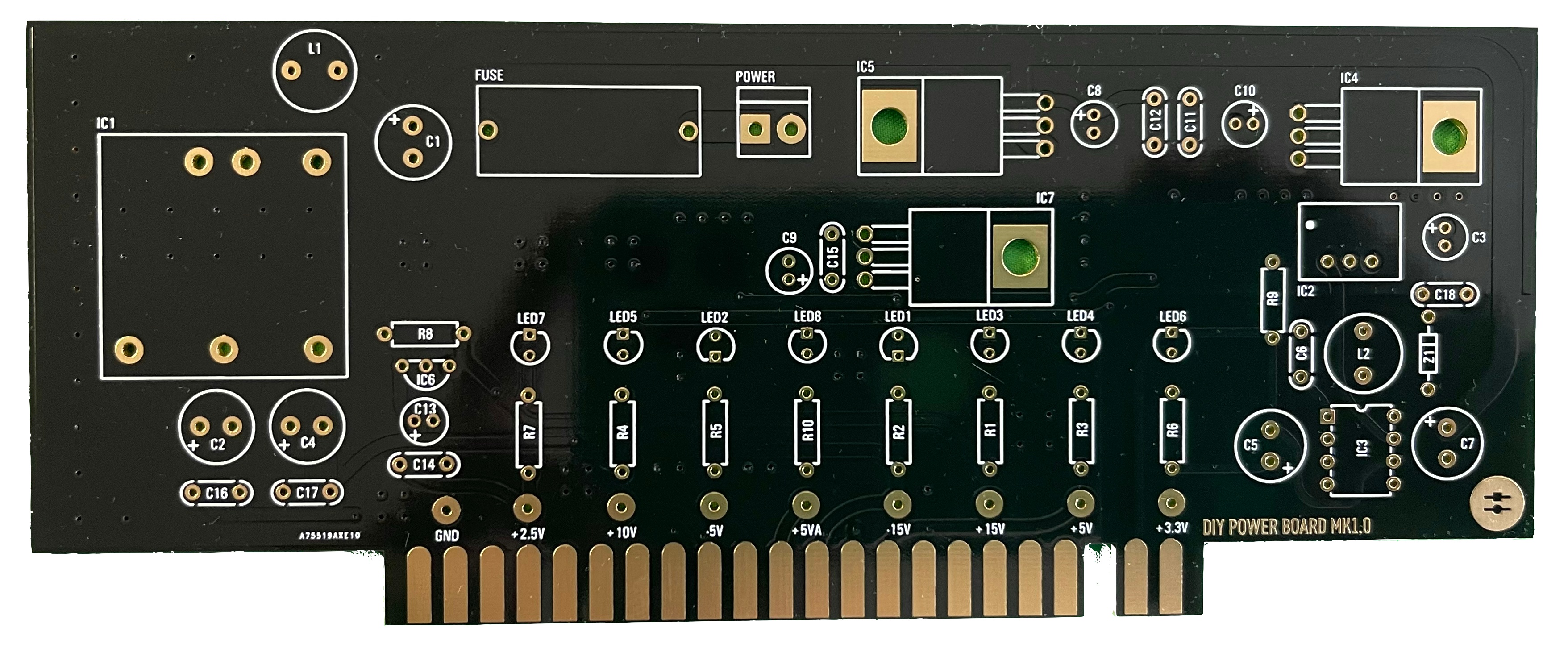
- install the resistors and diodes
- install the ceramic capacitors (not the electrolyte caps yet)
- install the TO-220 regulators (IC4, IC5, IC7), the black isolated regulators do not match with the pcb holes, its not important. bend the pins as short as possible that they can be soldered from the rear-side of the pcb
- install IC3 - I prefer without a socket for better thermal regulation, but should be fine with a socket too.
- install the electrolyte caps
- install the LEDs - LED orientation - the square pad is ground (short leg) its the flat side of the LED designator
- install the fuse socket and MTA 156 2pole header
- install the DC-DC bricks (IC1, IC2)
- Double check the IC orientation and part values, Capacitor polarity
- wash the PCB carefully and let they dry over night
- optional - use a bench psu for testing with current limiter 12v/250mA don't use a smaller current limit to avoid problems while start, the 250mA is a given value without any devices connected
- must do: all LEDs must be on, check against the given PCB voltages - all voltages must be correct
- Install the Heatsink by the self adhesive tape and push the heatsink against the DC-DC for 20-30seconds (new task since 24.Nov.2022)
first test on a bench PSU with current limit at 12v/200mA
...