| Panel | ||||||||||
|---|---|---|---|---|---|---|---|---|---|---|
| ||||||||||
Projecttitel: ISE-NINStatus:
Startdate: 26th Aug.2022Duedate: 15th Sep.2022Last page update:1026.Dec..2022Feb.2023 BOM correctedManufacture link: https://black-corporation.comModwiggler: https://www.modwiggler.com/forum/viewtopic.php?t=265268Facebook Build Group: https://www.facebook.com/groups/517757979447099Facebook User Group: https://www.facebook.com/groups/800008500661600Gearspace : https://gearspace.com/board/electronic-music-instruments-and-electronic-music-production/1353336-black-corporation-ise-nin-8-voice-analogue-synthesizer-15.html |
| Table of Contents | ||||
|---|---|---|---|---|
|
...
| Panel | ||||
|---|---|---|---|---|
| ||||
Before you built the ISE-NIN kit:
|
...
...
BOM:
ISE-NIN-BOM-REV1.0.4.xlsx uploaded 26.Feb.2022 (PSU alternativ part was swapped in line 198/199)
ISE-NIN-BOM-REV1.0.3.xlsx uploaded 10.Dec.2022
ISE-NIN-BOM-REV1.0.2.xlsx uploaded 24.Nov.2022
...
Important Information before you start assembling:
| Info ID | Date | Location | Type | Issue | Tip | ||
|---|---|---|---|---|---|---|---|
| 1 | 13. Aug.2022 | Hardware Board | INFO | minimize Slider/Potentiometer malfunctions Soldering Info | when you install the sliders, DO NOT solder all pins successively, solder only one pin at the top and the bottom and proceed to the next slider, when you have installed all of them - solder the next single pin of each slider. this has to be respected with potentiometers too. The Sliders and Potentiometers have lubrication inside which is sensitive to heat and can be easily damaged (this mistake was made in many Syncussion clones ) | ||
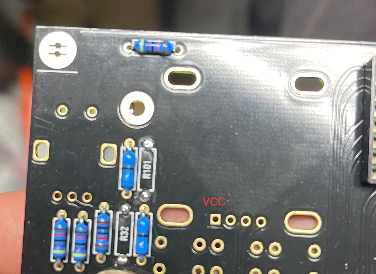
| 2 | 13. Aug.2022 | Hardware Board | INFO | OLED Selection and R101/R32 - R100/R102
| when you have an OLED with the PINOUT: VCC-GND-SCL-SDA install R100 and R102 (0 Ohm - a bridge) (R32/R101 must be left empty) in case you have an OLED with the PINOUT: GND-VCC-SCL-SDA install R101 and R32 (0 Ohm -a bridge) | ||
| 3 | 13. Aug. 2022 | All pcbs | INFO | some IC Sockets do not point in the same direction as the others, it´s a known issue that people install ICs backwards | Double and triple check every IC orientation - maybe 80% of all device malfunctions happen because of that and often end in very expensive repairs | ||
| 4 | 13. Aug.2022 | Hardware Board, PSU, Mainboard | INFO | the LEDs do not work | when you build the device - its important to start with the power supply - here you can test the LED orientation. never trust the vendor pinout for LEDs. normally the long LED leg is the positive end (anode) (but some circuits are powered from negative rails and GND is the positive end in this case- just as an explanation) | ||
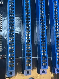
| 5 | 13. Aug. 2022 | Mainboard | INFO | solder the pins on the Edgecard holder where you find the white stripe on the PCB -
| you can't install the edge cards in the wrong way | ||
| 6 | 14.Aug.2022 | Mainboard | INFO | keep the length of the power cable as short as possible - that minimizes the risk that you accidentally put the PSU card in a voice card slot | |||
| 7 | 14.Aug.2022 | Hardware Board | INFO | pay attention to "Pot23 - Volume" (upper right corner) this is the one non-center detent pot. | |||
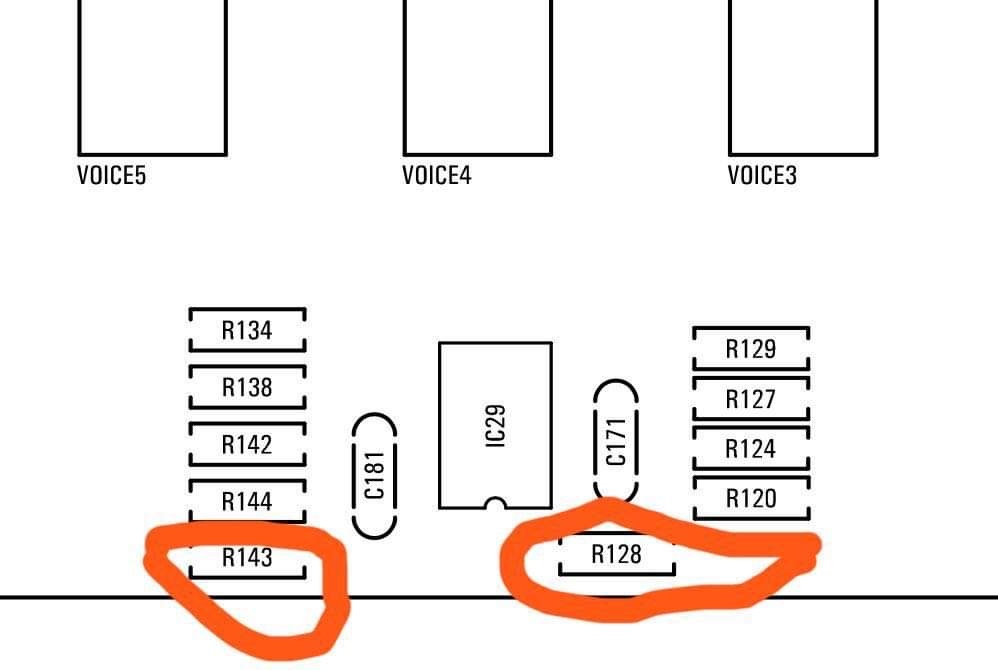
| 8 | 14.Aug.2022 | Mainboard | BUG | BOM1.0 Change- fixed in BOM v1.0.1 R103, R104, R105 = 330K (was 30k in BOM rev 1.0.0) R128, R143 = 10K (was 30k in BOM rev1.0.0) R137, R146 = 10K. (was 20k in BOM rev1.0.0)
| fixed on 24.Sep.2022 in BOM 1.0.1 | ||
| 9 | 03.Oct.2022 | Parts | INFO | the 2N3094 on the Voicecards must be a matched pair (within 2mV vbe) | A. if you are a pro builder.. you still have a device to match trannys. B. you can order or build a tester C. you order matched pairs by me or thonk https://www.diysynth.de/diy-components/aktive-bauteile/gematche-transistoren. | html?language=de||
| 10 | 18 April 2023 | PSU | BUG | R8 220R on the PSU goes very hot - it affect the lifetime of this part | workaround: change to 2Watt 220R 1% resistor metalfilm or try 470R 0,6watt 1% metalfilm a solution or other workaround is in test (TL431 source from the 5V regulator instead from 15v) |
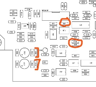
PCB Scan Pictures (thanks Janne.I)
...
| Panel | ||
|---|---|---|
| ||
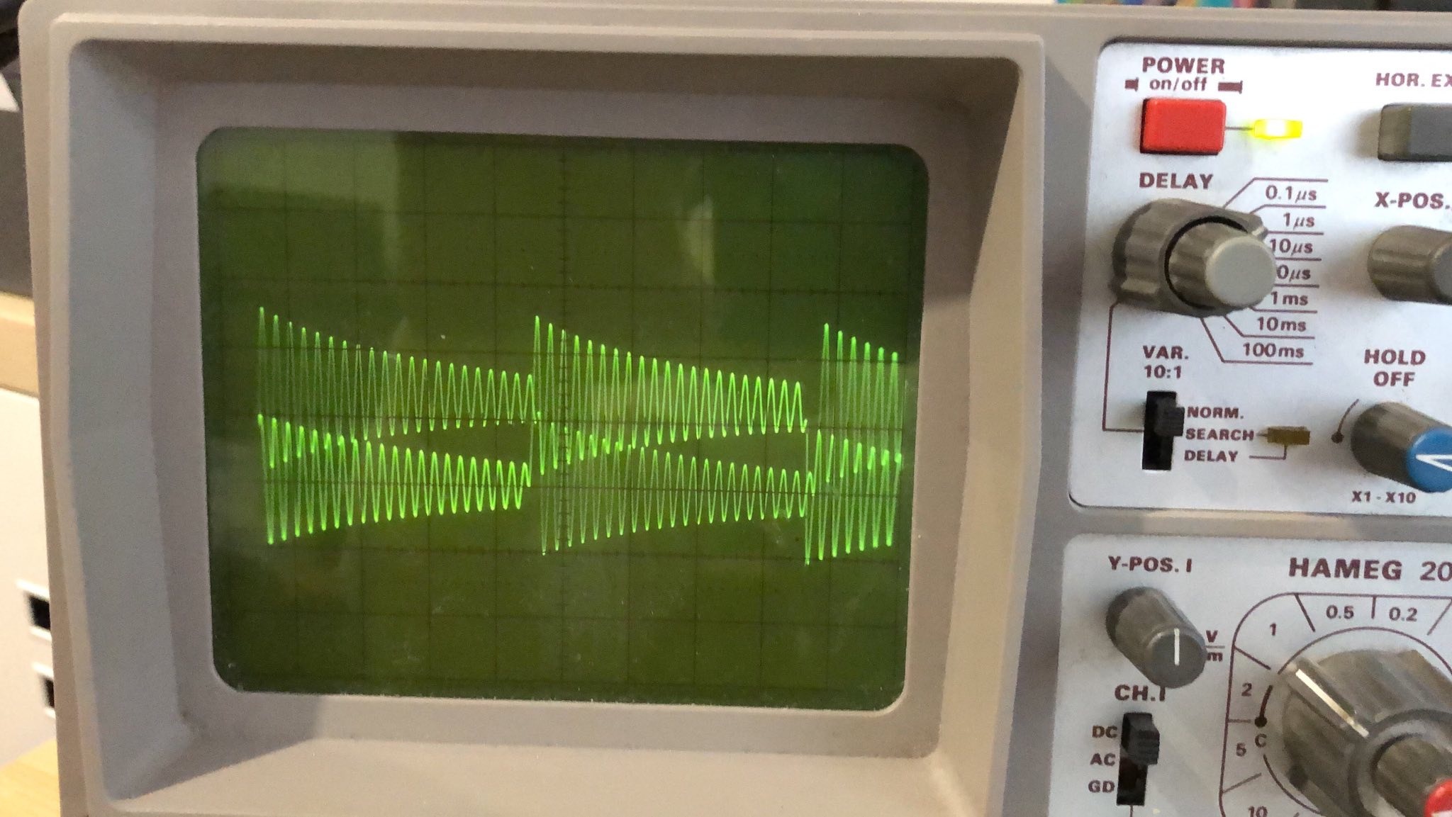
Here is a step by step guide to calibrate the filter resonance: (ONLY AFTER that you need to calibrate filters in further step)It´s recommend turning the resonance trimmer TR1 fully clockwise on each voicecard to make this procedure as easy as possible! 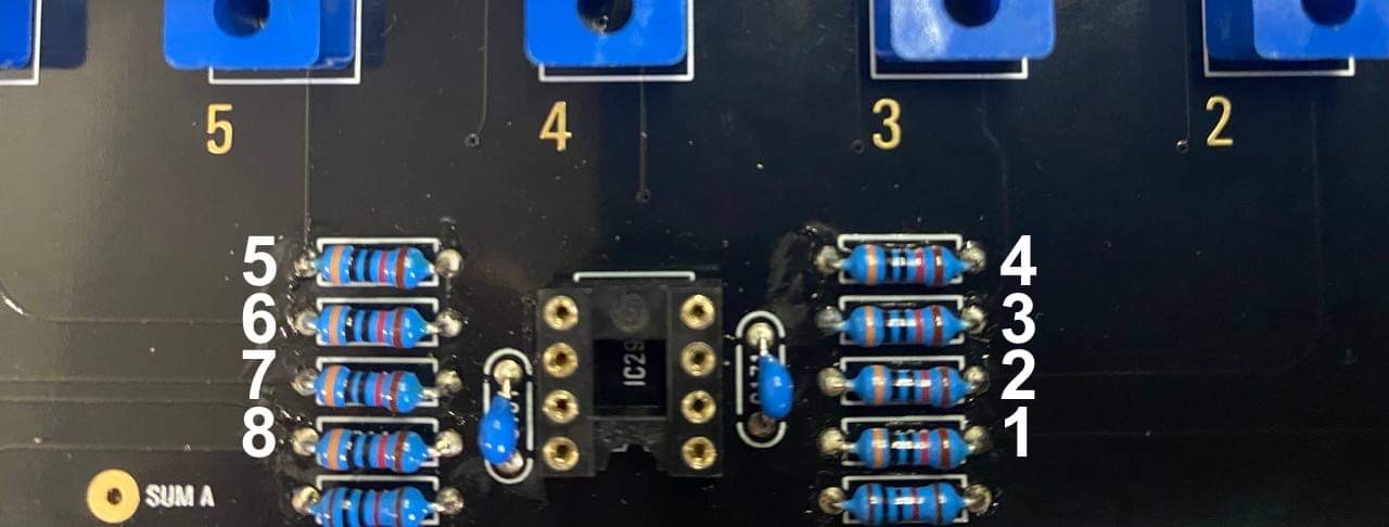 The best way is to use 8 resistors on the mainboard for making a measurement. 1. Warm up your unit about 30-40 mins 2. turn on ISE-NIN, Go to menu (press shift (grey cap button) + Back (middle button under the display), then calibration, choose resonanceCROSSMOD then press SHIFT and press the encoder, this will add the hidden RESONANCE and CROSSMOD TRIM function (its hidden since prebuilt units do not need this) (The display should read: "card 1" and you should hear a test tone through the outputs (for the next voice card you can press the "next (Back)" button to cycle through the voice cards) 3. Connect a Scope probe on the Mainboard, to the resistor of the card which you calibrate , set your oscilloscope to "timebase 0.5ms/cm" and "1V/cm" (on DMM: 0.5V -1V is fine too, depends on your scope screen resolution - some new scopes are HD resolution in 720p or more and the ADC are very accurat) 4. You should see the filter signal on your scope. If you have turned the trimmer fully clockwise the signal should be- and sound distorted. now turn the "resonance" trimmer TR1 on the Voicecard anti- clockwise until you get a clean signal as in the picture below (The difference of maximum and minimum amplitude in one cycle has to be 4-times.) make sure to have enough gain otherwise the Filter calibration step will fail as described in next section. Comment from Black Corp: "We especially made all settings in resonanse calibration how they should be (square, cutoff, 12db etc)."
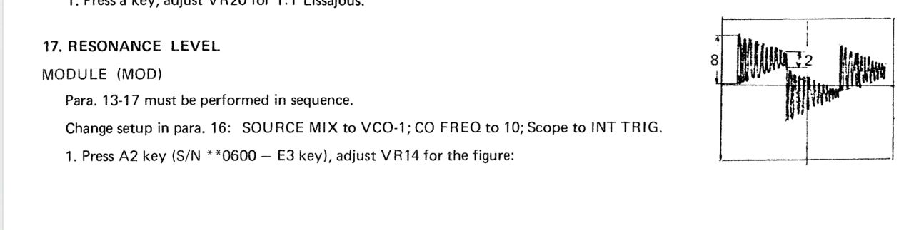
Congratulations, you have successfilly calibrated the filter resonance for all of the voices! Resonance calibration Method according to the Roland Jupiter-8 service manual (not recommended yet → use above method!!!):Go into MENU, CALIBRATION, RESONANCE. Follow these steps from the Jupiter 8 manual, turning Trim1 for each voice (or see below):
Workaround or turn Trim TR1 until the self oscillation is off on each voice. you can switch between the cards using the switch button on the mother board. |
...
| Panel | ||
|---|---|---|
| ||
MENU, CALIBRATION, choose CROSSMOD then press SHIFT and press the encoder, this will add the hidden RESONANCE and CROSSMOD TRIM function (its hidden since prebuilt units do not need this)CROSS MOD TRIM, connect USB out of ISENIN to computer, turn on ableton select ise-nin as input, put a tuner oh the channel and adjust it to 220hz with the Offset Trimmer for each voice, switch between voices with the switch button. |
...