| Panel | ||||||||||
|---|---|---|---|---|---|---|---|---|---|---|
| ||||||||||
Projecttitel: ISE-NINStatus:
Startdate: 26th Aug.2022Duedate: 15th Sep.2022Last page update:2611.FebNov.2023BOM corrected- VCO Sync failureManufacture link: https://black-corporation.comModwiggler: https://www.modwiggler.com/forum/viewtopic.php?t=265268Facebook Build Group: https://www.facebook.com/groups/517757979447099Facebook User Group: https://www.facebook.com/groups/800008500661600Gearspace : https://gearspace.com/board/electronic-music-instruments-and-electronic-music-production/1353336-black-corporation-ise-nin-8-voice-analogue-synthesizer-15.html |
...
| Panel | ||||||||
|---|---|---|---|---|---|---|---|---|
| ||||||||
This guide is a best practice guide and I'm not responsible for any damage, or product quality. Please respect your local laws/regulation for handling of electronics/electricity electricity. I'm not responsible for damages, failures with your build. Do not try to build this device without basic knowledge of synthesizers. You need experience. |
| Panel | ||||||||
|---|---|---|---|---|---|---|---|---|
| ||||||||
Before you built the ISE-NIN kit:
|
...
Currently identified Errors / Omissions / Errata:
| Issue ID | Date | Location | Type | Identified issue | Resolution | related for development | affected PCB version | fixed Version |
|---|---|---|---|---|---|---|---|---|
| 1 |
|
| -- | BOM 1.02 | ||||
| 2 | 30. Aug 2022 | BOM - Mainboard | INFO | the 220uF caps on the Mainboard are BI-POLAR - | respect the BOM partnumber | |||
| 3 | 07 Sep. 2022 | Hardware Board | BUG | there's no Pinout described on the Hardware Board for the OLED - | please read the INFO section in the next table on "OLED selection" carefully | can be improved with better silkscreen information | 1.0 | |
| 4 | 13 Sep. 2022 | BOM: Voices | INFO | the Mouser BOM shows 32x 240pF C0G capacitors for the Voices - used in the OTA Filter. These are 10% tolerance. | you can change the capacitors to Polypropylene, Silver MICA, Styrene - with 1-2.5% or match good capacitors in this range with an LCR meter (check the data sheets of the meter) | - | - | - |
| 5 | 13.Sep.2022 | create a Silkscreen for MTA156 Powerheader pinout | 1.0 | |||||
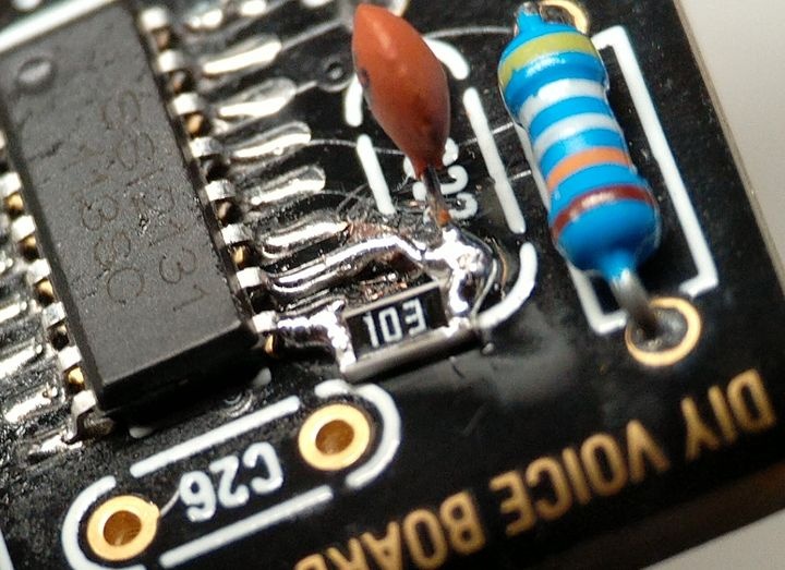
| 6 | 29.Oct.2022 | Voices | BUG | Sync doesn't work correctVCO Sync use the wrong waveform | remove on every Voicecard IC3 (TL064). bend Pin 12 of the TL064 outwards, install the IC3 back in the IC socket and solder a resistor leg from Pin12 to Pin10 as shown: 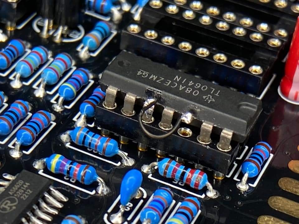 | fix the PCB routing | 1.0 | |
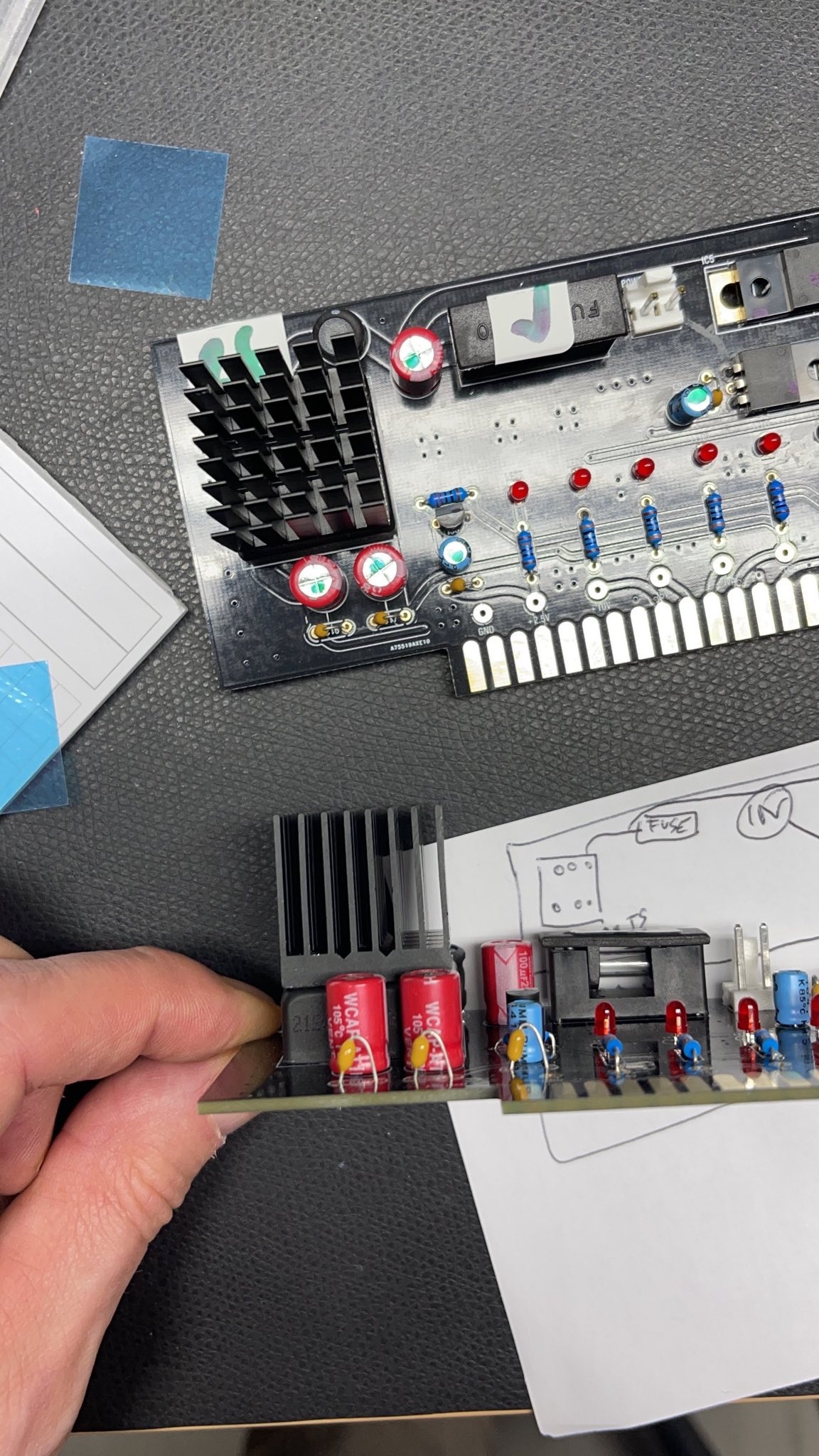
| 7 | 17.Nov.2022 | PSU card | INFO | The DC-DC converter goes very hot after 30minutes, but its within the data sheet specs (65degrees Celsius is the max. operation). The 65 degrees can be reached in Summer or other conditions (few hours operating time) But for longterm stability of the components, I highly recommend the usage of a big cooler | install a 25x25mm cooler with an high of minimum 20mm. I found on tme.eu a product with self adhesive foil and 24.5mm height. the temperature of the DC.DC converter is 51 degrees after an hour on the regulator and 43 degrees on the cooler. TME Part nr. ATS-55250W-C1-R0 |
| 1.0 | BOM 1.02 is updated for this !! |
Important Information before you start assembling:
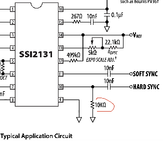
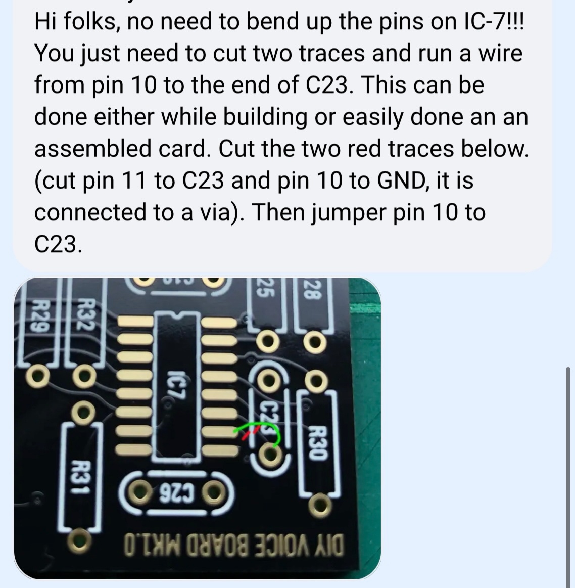
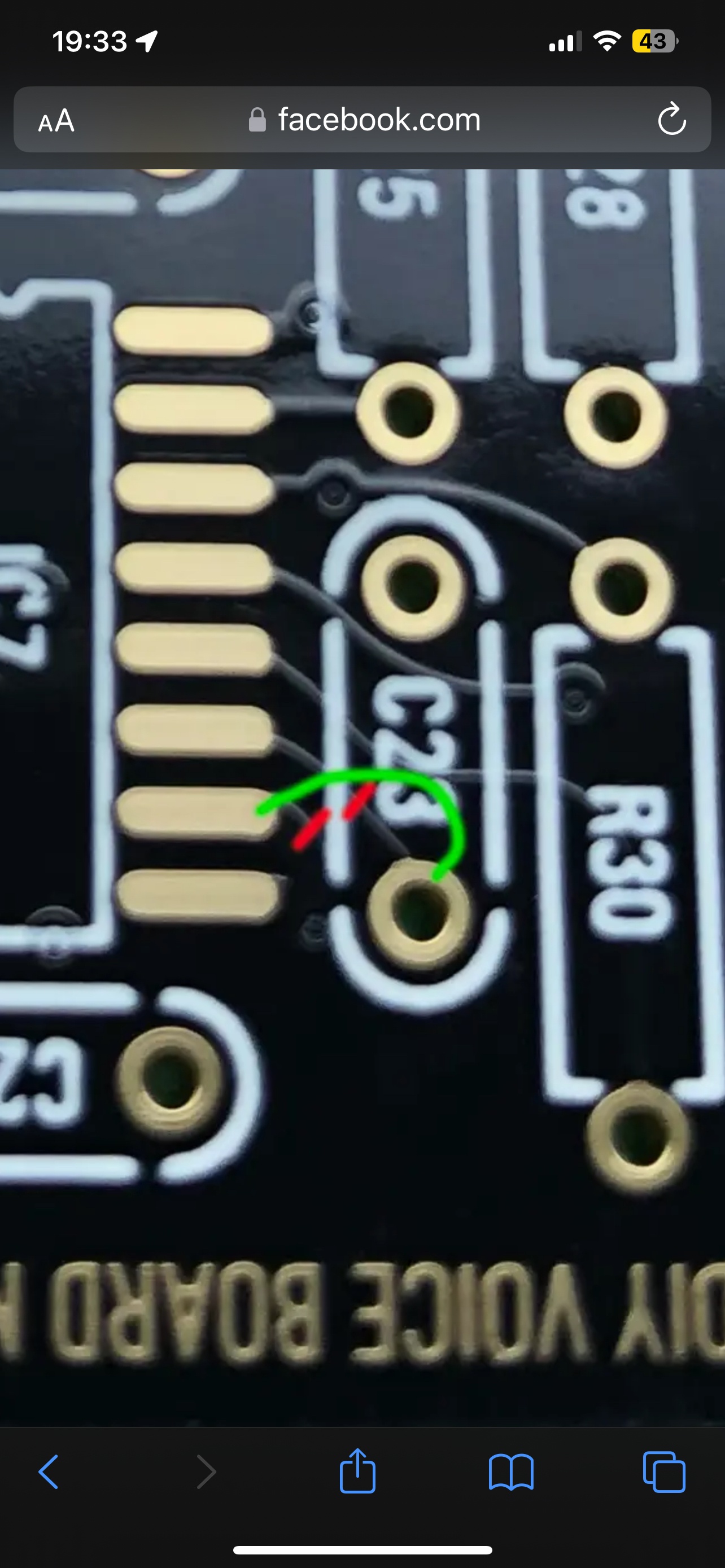
| 8 | 08.Oct.2023 update on 04.Nov.2023 | all voices | BUG | the Sync function must be fixed there's a "stepping" in the sync sound. respect Step 6 from the Issue list too. | update: 04.November 2023 there's a additional 10K resistor to be installed, which isn't described in the notes here. Connect an additional 10K Resistor to GND via PIN10. This resistor is shown in the ssi2131 data sheet.
a Facebook user made the change in a other way: "This is how i did the sync fix, i only had 1206 10k resistors, would be perfect with an 0805. Will put a drop of paint there, it will look nice (from a distance
| 1.0 | ||
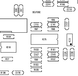
| 9 | 15.March 2024 | Mainboard | BUG | Volume Potentiometer, only at the first 50% of rotation is the Volume gain impact given. at around 50-100% is only few dB volume change. | from BC officially: "Hey Everyone, here is the solution to the DIY volume issue. On the MB (motherboard), replace resistors R99, R100, R101, R102 with 100k 1%. click to enlarge:Voluem pot BUG
| change the BOM | 1.0 |
Important Information before you start assembling:
| Info ID | Date | Location | Type | Issue | Tip | |||||||||||||||||||||||||||
|---|---|---|---|---|---|---|---|---|---|---|---|---|---|---|---|---|---|---|---|---|---|---|---|---|---|---|---|---|---|---|---|---|
| 1 | 13. Aug.2022 | Hardware Board | INFO | minimize Slider/Potentiometer malfunctions Soldering Info | when you install the sliders, DO NOT solder all pins successively, solder only one pin at the top and the bottom and proceed to the next slider, when you have installed all of them - solder the next single pin of each slider. this has to be respected with potentiometers too. The Sliders and Potentiometers have lubrication inside which is sensitive to heat and can be easily damaged (this mistake was made in many Syncussion clones ) | |||||||||||||||||||||||||||
| 2 | Info ID | Date | Location | Type | Issue | 1 | 13. Aug.2022 | Hardware Board | INFO | minimize Slider/Potentiometer malfunctions Soldering Info | when you install the sliders, DO NOT solder all pins successively, solder only one pin at the top and the bottom and proceed to the next slider, when you have installed all of them - solder the next single pin of each slider. this has to be respected with potentiometers too. The Sliders and Potentiometers have lubrication inside which is sensitive to heat and can be easily damaged (this mistake was made in many Syncussion clones ) | 2 | 13. Aug.2022 | Hardware Board | INFO | OLED Selection and R101/R32 - R100/R102
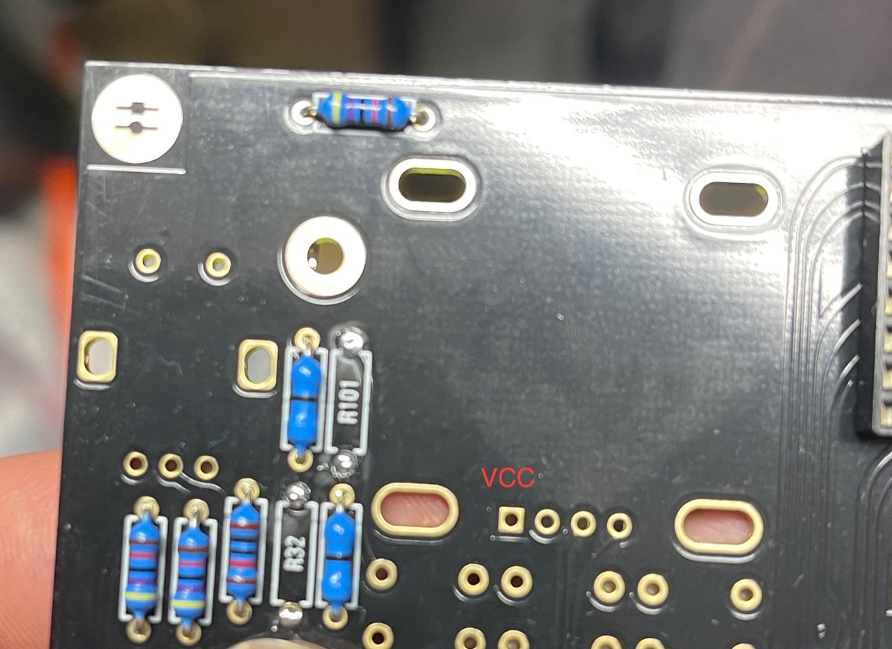
| when you have an OLED with the PINOUT: VCC-GND-SCL-SDA install R100 and R102 (0 Ohm - a bridge) (R32/R101 must be left empty) in case you have an OLED with the PINOUT: GND-VCC-SCL-SDA install R101 and R32 (0 Ohm -a bridge) | 3 | 13. Aug. 2022 | All pcbs | INFO | some IC Sockets do not point in the same direction as the others, it´s a known issue that people install ICs backwards | Double and triple check every IC orientation - maybe 80% of all device malfunctions happen because of that and often end in very expensive repairs | 413. Aug.2022 | Hardware Board | , PSU, MainboardINFO | the LEDs do not workOLED Selection and R101/R32 - R100/R102
| when you | build the device - its important to start with the power supply - here you can test the LED orientation.have an OLED with the PINOUT: VCC-GND-SCL-SDA install R100 and R102 (0 Ohm - a bridge) (R32/R101 must be left empty) in case you have an OLED with the PINOUT: GND-VCC-SCL-SDA install R101 and R32 (0 Ohm -a bridge) | |||
| 3 | 13. Aug. 2022 | MainboardAll pcbs | INFO | some IC Sockets do not point in the same direction as the others, it´s a known issue that people install ICs backwards | Double and triple check every IC orientation - maybe 80% of all device malfunctions happen because of that and often end in very expensive repairs | |||||||||||||||||||||||||||
| 4 | 13 | you can't install the edge cards in the wrong way | 6 | 14. Aug.2022 | Hardware Board, PSU, Mainboard | INFO | keep the length of the power cable as short as possible - that minimizes the risk that you accidentally put the PSU card in a voice card slot | 7 | 14.Aug.2022 | Hardware Board | INFO | pay attention to "Pot23 - Volume" (upper right corner) this is the one non-center detent pot. | the LEDs do not work | when you build the device - its important to start with the power supply - here you can test the LED orientation. never trust the vendor pinout for LEDs. normally the long LED leg is the positive end (anode) (but some circuits are powered from negative rails and GND is the positive end in this case- just as an explanation) | ||||||||||||||||||
| 5 | 13 | 8 | 14. Aug. 2022 | Mainboard | BUG | fixed on 24.Sep.2022 in BOM 1.0.1 | 9 | 03.Oct.2022 | Parts | INFO | the 2N3094 on the Voicecards must be a matched pair (within 2mV vbe) | INFO | solder the pins on the Edgecard holder where you find the white stripe on the PCB -
| you can't install the edge cards in the wrong way | ||||||||||||||||||
| 6 | 14.Aug.2022 | Mainboard | INFO | keep the length of the power cable as short as possible - that minimizes the risk that you accidentally put the PSU card in a voice card slot | ||||||||||||||||||||||||||||
| 7 | 14.Aug.2022 | Hardware Board | INFO | pay attention to "Pot23 - Volume" (upper right corner) this is the one non-center detent pot. | ||||||||||||||||||||||||||||
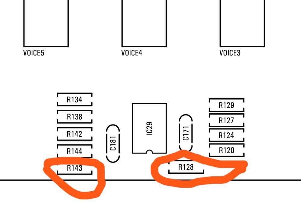
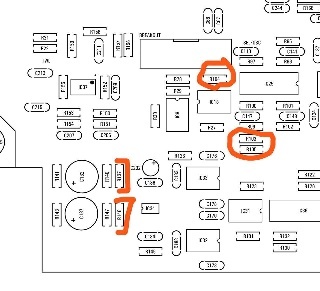
| 8 | 14.Aug.2022 | Mainboard | BUG | BOM1.0 Change- fixed in BOM v1.0.1 R103, R104, R105 = 330K (was 30k in BOM rev 1.0.0) R128, R143 = 10K (was 30k in BOM rev1.0.0) R137, R146 = 10K. (was 20k in BOM rev1.0.0)
| fixed on 24.Sep.2022 in BOM 1.0.1 | |||||||||||||||||||||||||||
| 9 | 03.Oct.2022 | Parts | INFO | the 2N3094 on the Voicecards must be a matched pair (within 2mV vbe) | A. if you are a pro builder.. you still have a device to match trannys. B. you can order or build a tester C. you order matched pairs by me or thonk https://www.diysynth.de/diy-components/aktive-bauteile/gematche-transistoren.html?language=de | |||||||||||||||||||||||||||
| 10 | 18 April 2023 updated 23June 2023 | PSU | BUG | R8 220R 250mW on the PSU goes very hot - it affect the lifetime of this part and brings thermal noise in the circuits. | replace R8 (220R) with a 470R 1watt 1% metalfilm with 50ppm digikey: BC4533CT-ND a other untested workaround is in to remove the 220R and connect a wire thru 100R 1-2Watt to the the 5VA regulator output to the left TL431 (use the pad of the 220R). this workaround is only for people who know what they do - they dont need my help/infos to do this mod. | |||||||||||||||||||||||||||
| 11 | 08.Okt.2023 | all Voices | BUG | the Sync function must be fixed there's a "stepping" in the sync sound. respect Step 6 from the Issue list too. The Issie is reported in this list, because its easier to cut the trace before you have installed the SMT IC7 |
|
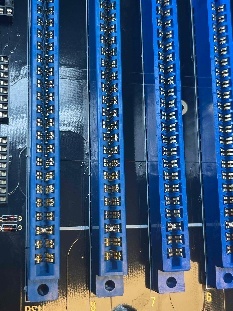
PCB Scan Pictures (thanks Janne.I)
...