...
| ID | Issue | Fix | date | fixed version |
|---|---|---|---|---|
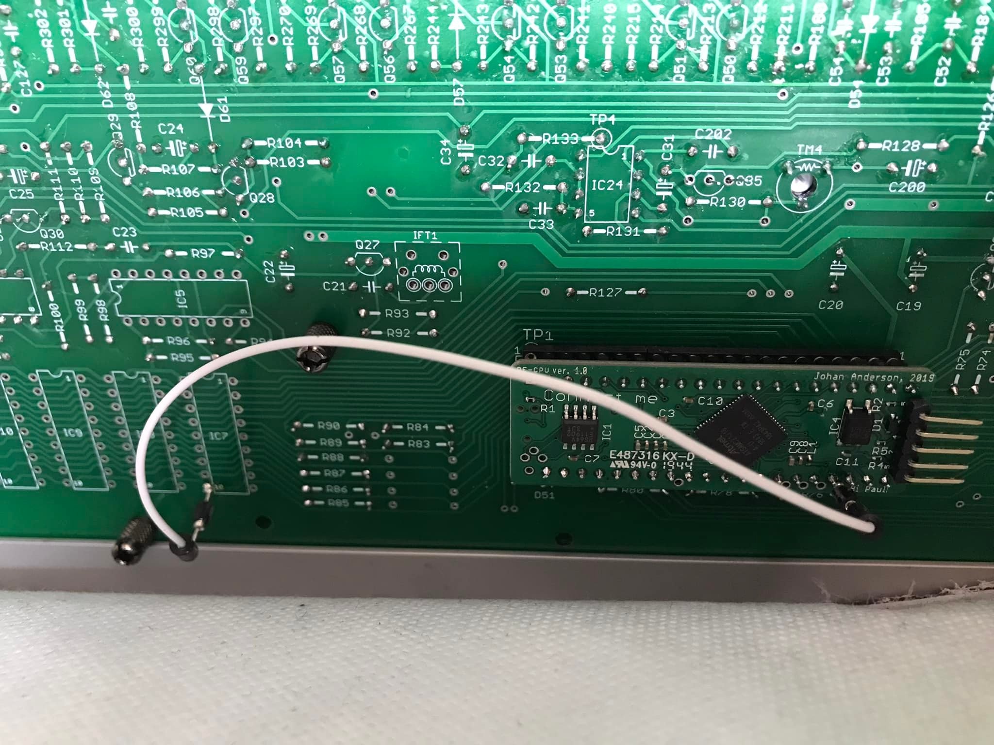
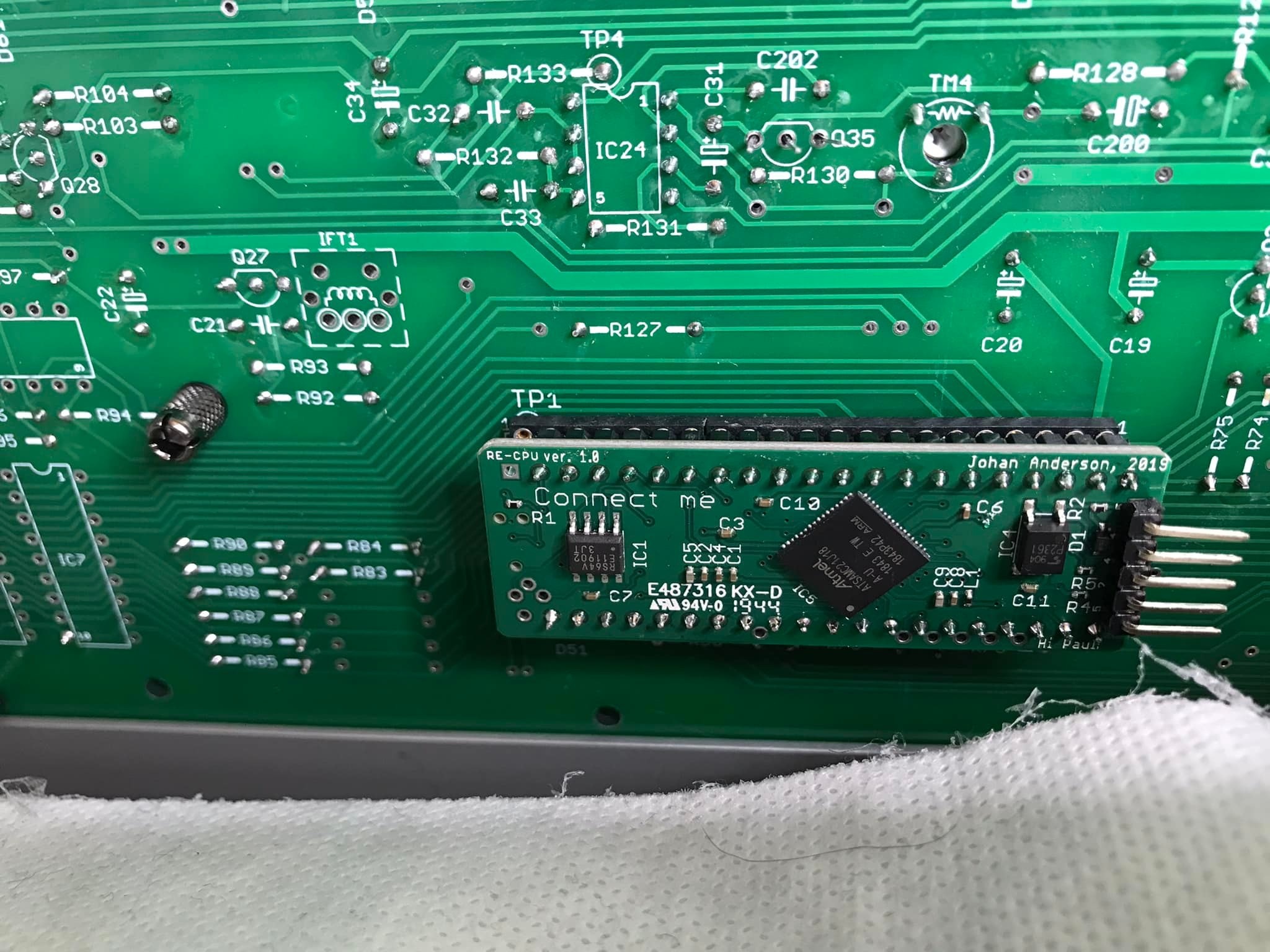
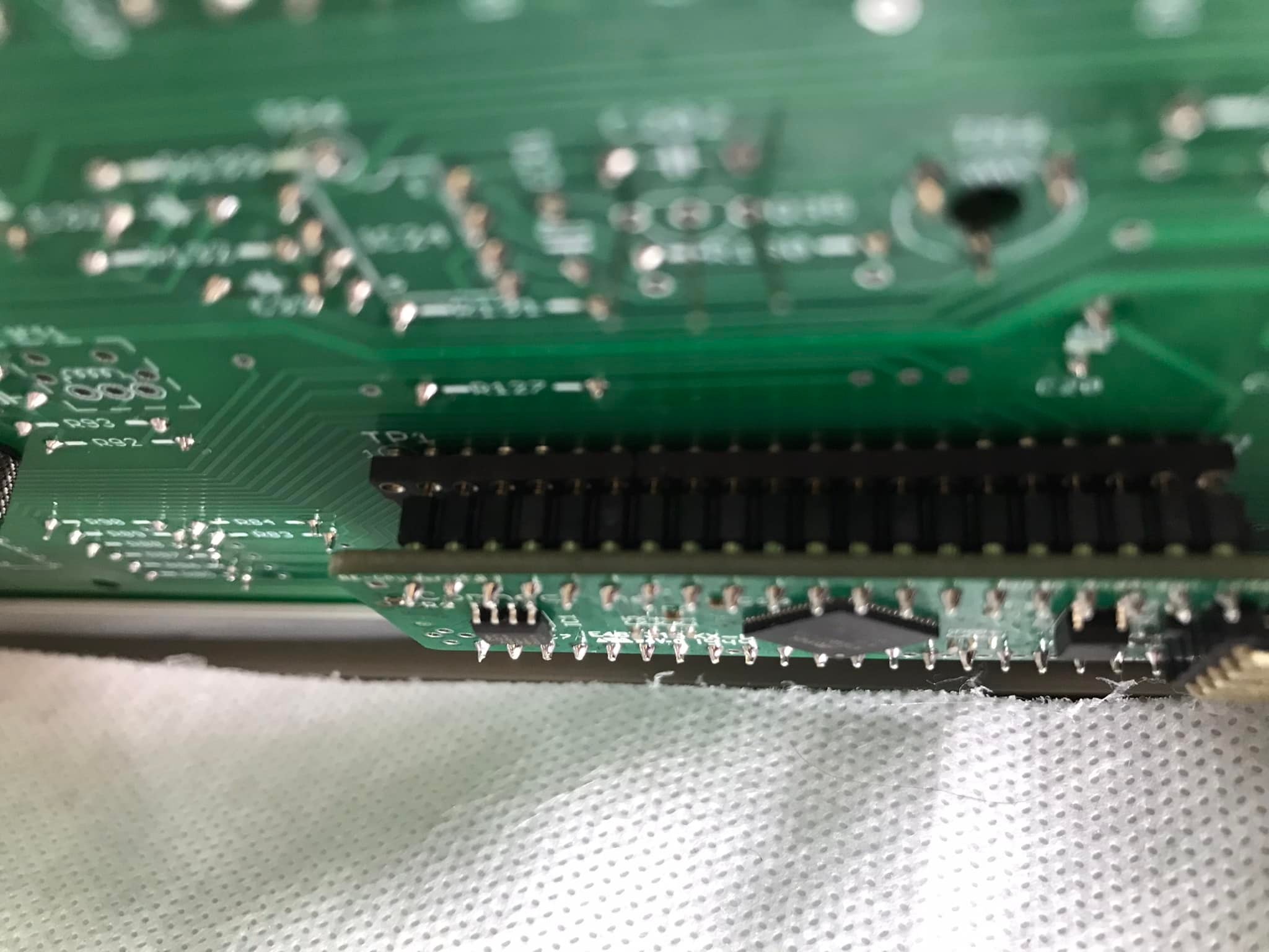
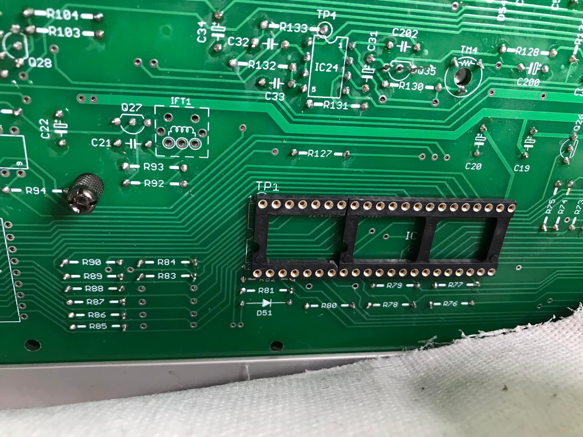
| 1 | CPU mounting | As you can see you also need to do a jumper wire between the solder point marked A on the pixie cpu and pin 10 (!WE pin) of *any* of IC 7,8,9 or 10 (they’re all connected to the same signal)
| 01/2022 | |
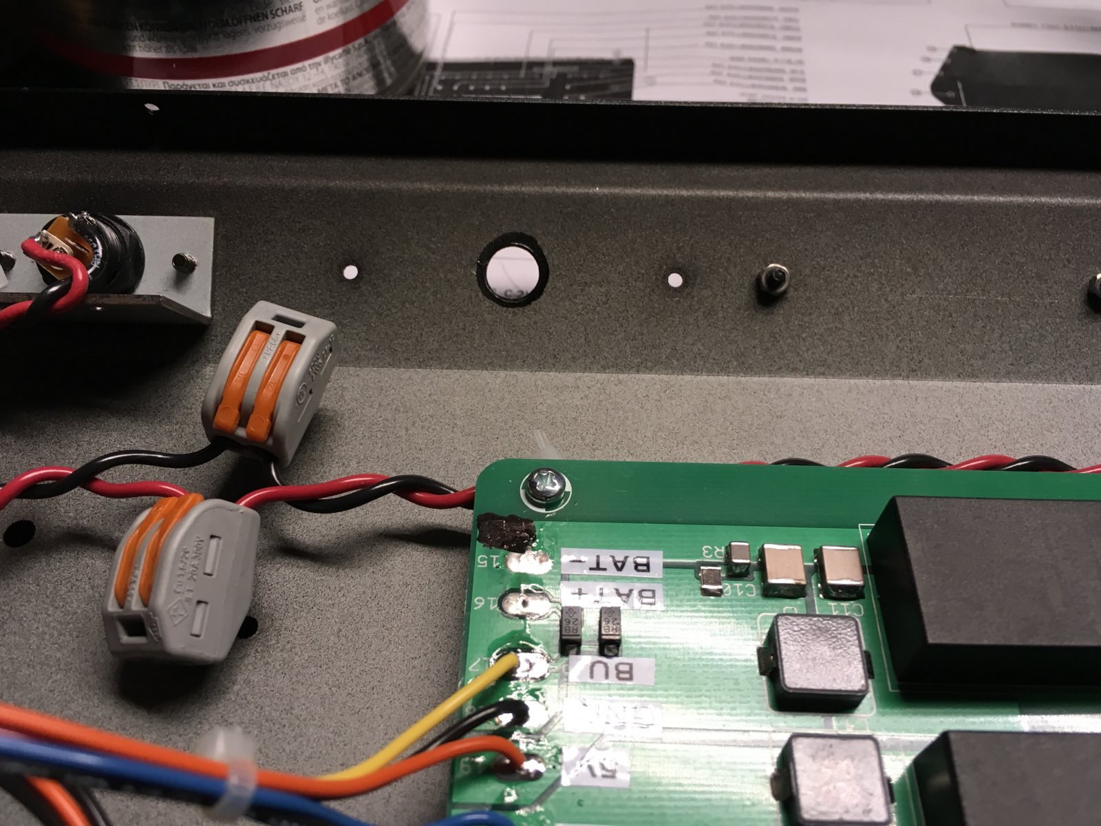
| 2 | PSU | Do not fit the DC jack on the PSU circuit board. Its not used and it is not wired correctly. use a cable for the jack as shown for example
| 01/2022 | |
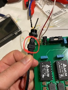
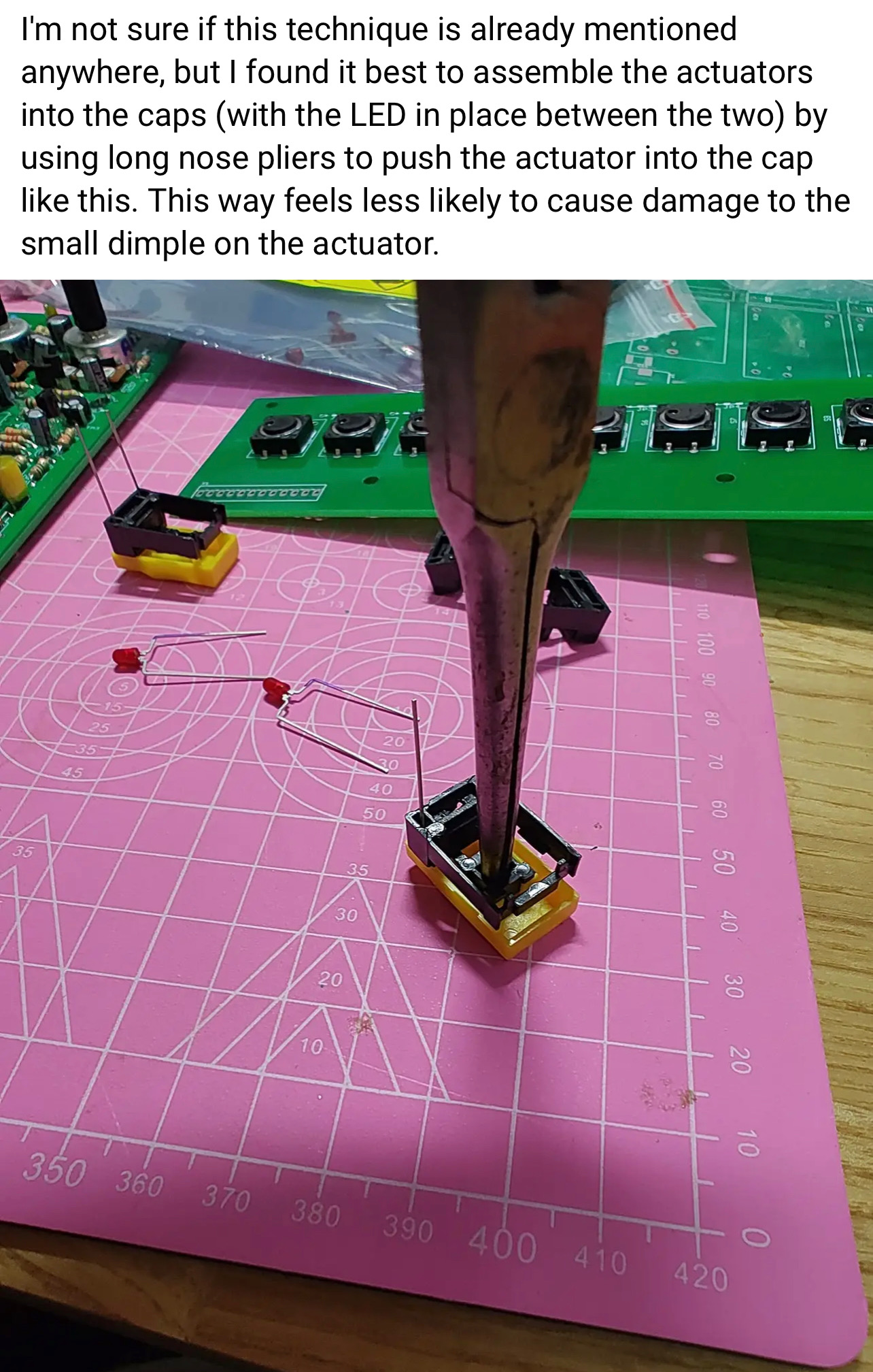
| 3 | Tactiles /caps install | heres a tip about the installation of the tactile caps:
| 01/2022 | |
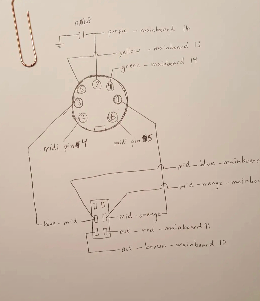
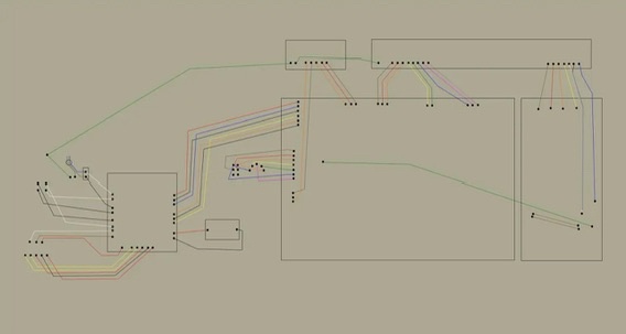
| 4 | MIDI WIRING |
| 11/2022 | |
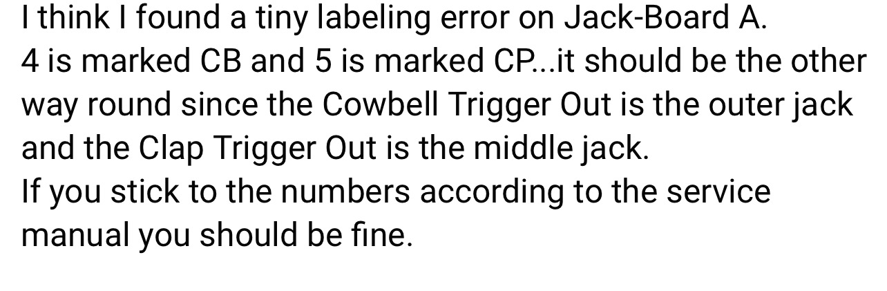
| 5 | Silkscreen wrong |
| 11/2022 | |
| 6 | Mainboard resistors - handclap |
in case you have the trimmer on solder side (recommended) install a resistor leg:
| 11/2022 | |
| 7 | guide /tip | for the voice board: first install all 1/8watt resistors on bottom of the pcb R1-9 are 1/8w or the switchboard do not fit use MLCC caps there and no IC socket. for IC1. when you have a solder frame: install the flat Trannys and ic sockets before you install the other parts for mainboard use for the noise transistor and muting trannys - ic socket pins to swap/change the trannys install good trimmers from nearside instead cheap trimmers from component side - better calibration possible | 11/2022 | |
| 8 | Transistors - sequencer failure | use sockets for the muting transistors. some users reported issues in combination with the pixie CPU, boot/start problems. the muting Transistors affect this - you can remove this. | 1.Dec.2022 | |
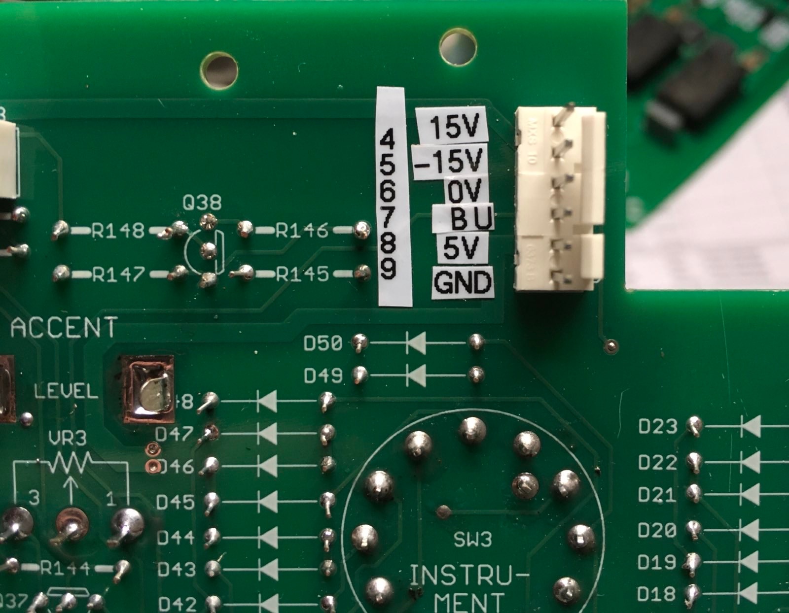
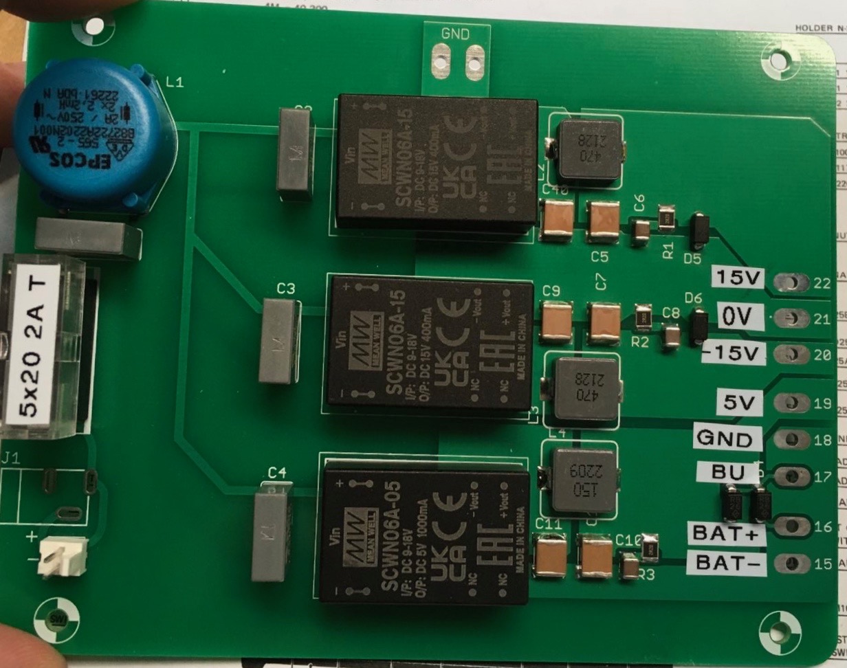
| 9 | Power Pinout |
credits by Martin.J.K - Thank you | 02.Jan.2023 | |
| 10 | general | install good trimmers on back side (solder side) - for easier calibration install the BA662 clone on solder side - in this was you can use a socket install the muting JFETS and noise Transitor on solder side for easier swapping install R333 on solder side to give you the opportunity to replace this with a trimmer (50k) to change the handclap sound.. | 02.Jan.2023 | |
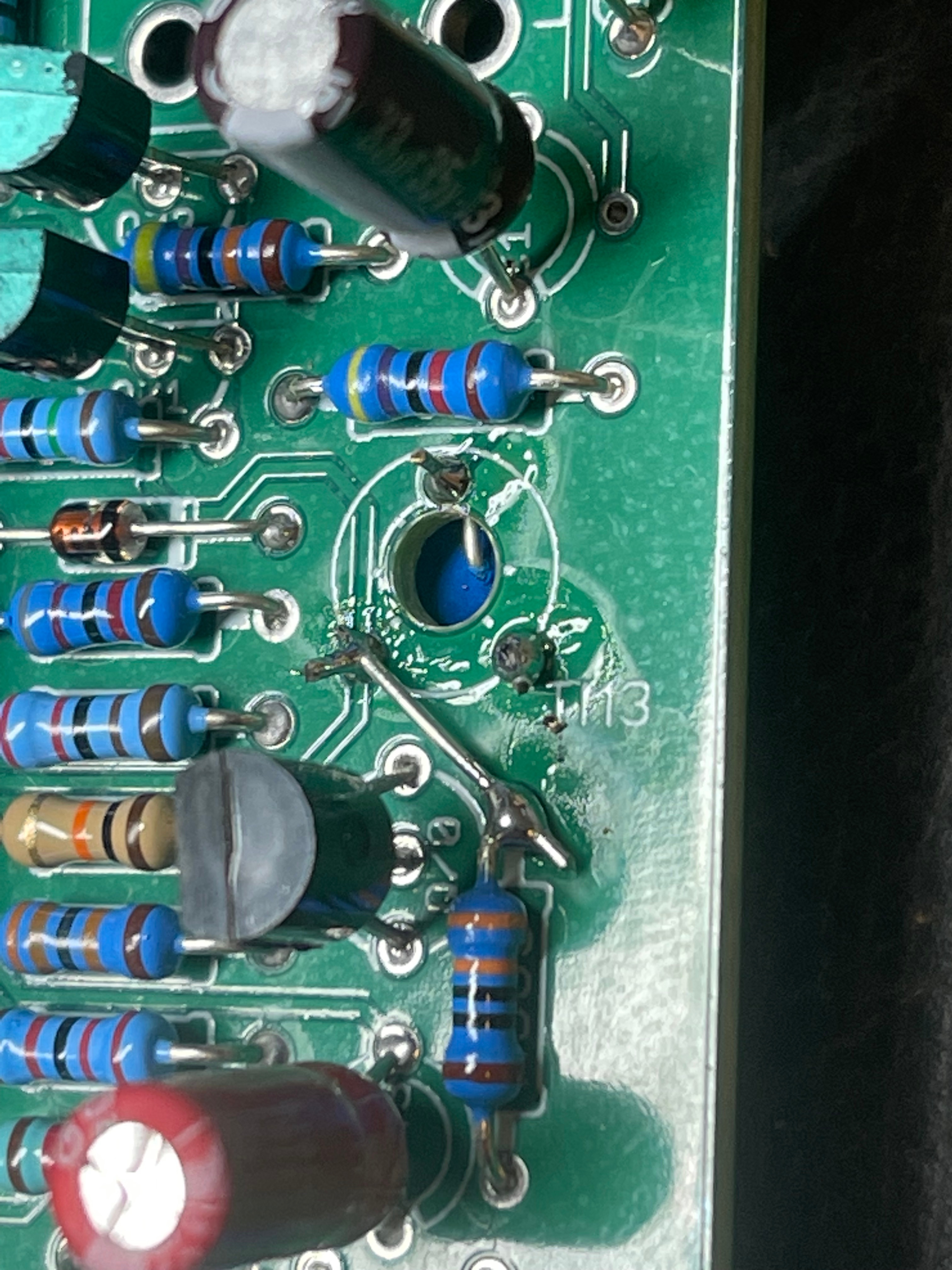
| 11 | bugfix | install a jumper as shown to get your 808 working as designed
| 03. Jan.2023 | |
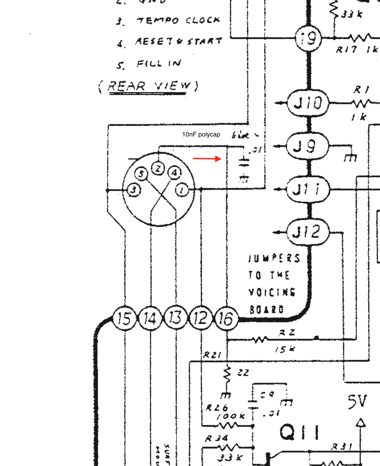
| 12 | capacitor on Sync jack | install a 10nF polyester cap or bipolar electrolyte cap at the sync jack or on the pcb
| ||
| 13 | clock calibration fix | remove C203 on mainboard (39nF) or your clock can't be calibrated in case you can't reach 120hz by trimmer end, install a 2M2 resistor in parallel on R43 | 04.Jan.2023 | |
| 14 | calibration |
| ||
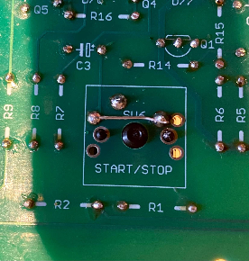
| 15 | wiring | some help.. found on FB
| ||
| 16 | calibration | change R376 to a 100K trimmer to adjust the clap reverb | ||
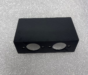
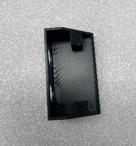
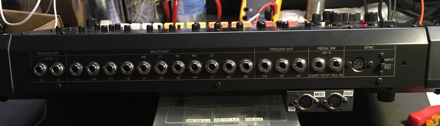
| 17 | MIDI connection MOD | the 3D printed part is available in my shop or print it myself (Resin preferred) just use 2 screws to mount this at the typenumber plate holes at the rear and drill a small for the MIDI cables.
|

| Change History | ||
|---|---|---|
|