Project
Projecttitel: RE-808
Status: IN PROGRESS
Startdate: 11/2021
Duedate: 12/2022
Last Update: 24.02.2023
Manufacture link: https://shop.re-303.com/product/re-808-bundle-3rd-run-advance-order/
source: Facebook.
after the RE-303, RE-606, RE-909 we have the RE-808 replica to build.
its an replica, which means 99.9% of everything is a replica - the pcbs, the case, the parts.
the only difference are replacement tactile switch of the sequencer.
but you can repair your TR-808 with the RE-808 parts.
Infos and groups:
https://www.facebook.com/groups/1095915370823319
BOM:
PCBs and some parts are available from the RE-303 shop
Cases and side panels are available from Kumptronics
Start/Stop cover and Tap cover of the switches are available from few Facebook users for now, maybe available later thru other suppliers.
Spacers (not in the BOM - but maybe supplied with the RE-808 case)
7 3 x 8mm FF Hex Spacer
4 3 x 10mm FF Hex Spacer
5 3 x 16.4mm FF Hex Spacer
3 3 x 18mm Hex Spacer
2 3 x 8mm MF Hex Spacer 8mm w/ 6mm Screw
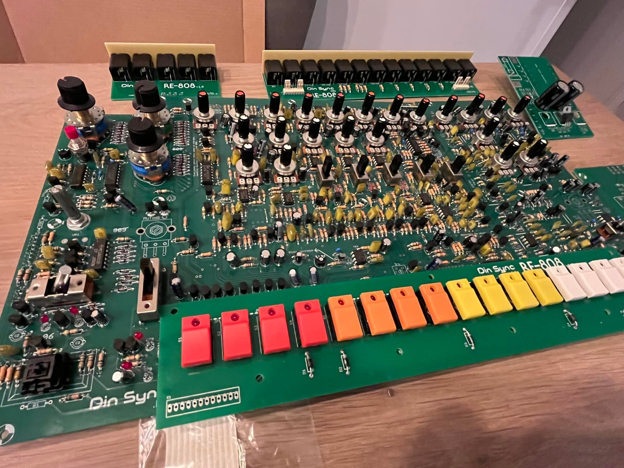
Buildguide: (uploaded 08.May.2022 by DSL-man)
RE-808 Switchboard Assembling v1.0.pdf
Alps Switches Modding Guide v1.0.pdf
RE-808-MYC-manual-midicable.pdf
NEW: RE-808 Case assembling guide. RE-808 assembly guide.pdf
Placement guide:
RE-808_Component_Placement_Guide_v1.0.0.pdf
Firmware Installation (on your own risk)
- turn on and send 808.sysxex with sysex librian tool
- turn off and on again
- send the boot loader sysex (1.30 version)
- turn off
- turn on while hold Step1 (all lets flashes like night rider mode)(some older boot loaders don't have the night rider mode)
- now send the REEMU 1.3.0 sysex
- machine restarts byself in 1.3.0 mode
- turn off and on the 808
- send the 808.sysex again
- reload the boot loader 1.4.3 in boot loader mode (hold step1) and upload the REEMU 1.4.3 sysex
Issue List
| ID | Issue | Fix | date | fixed version |
|---|---|---|---|---|
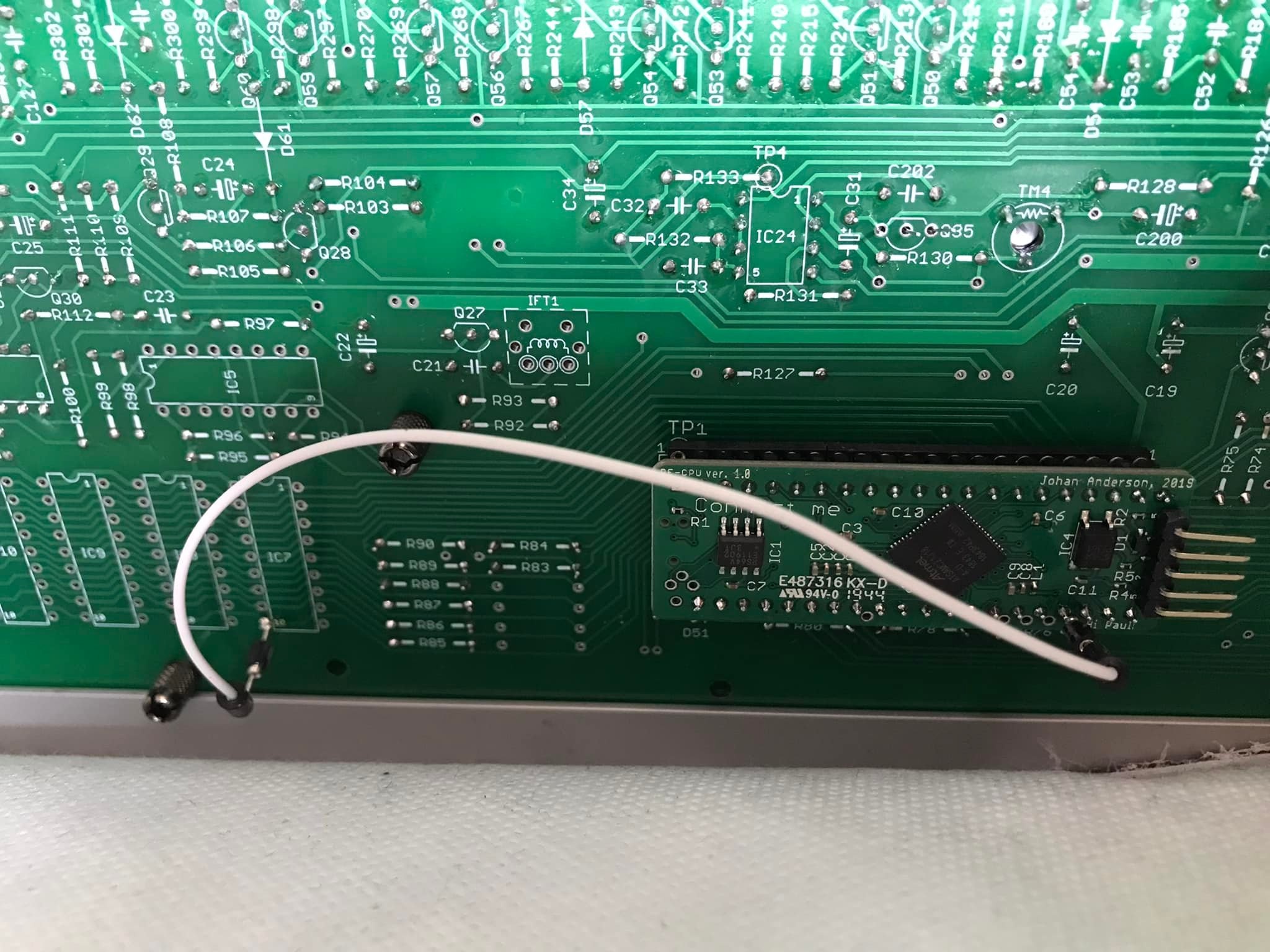
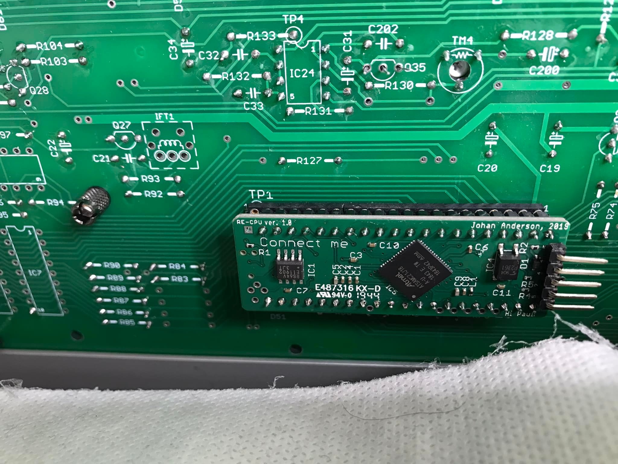
| 1 | CPU mounting | As you can see you also need to do a jumper wire between the solder point marked A on the pixie cpu and pin 10 (!WE pin) of *any* of IC 7,8,9 or 10 (they’re all connected to the same signal)
| 01/2022 | |
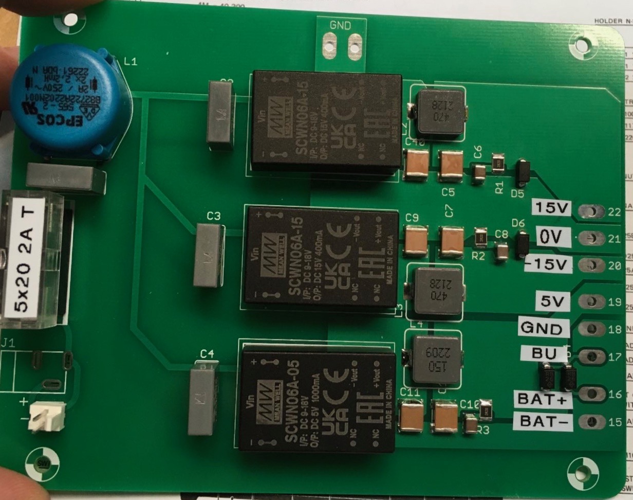
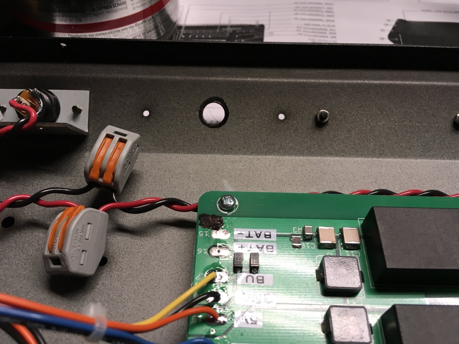
| 2 | PSU | Do not fit the DC jack on the PSU circuit board. Its not used and it is not wired correctly. use a cable for the jack as shown for example
| 01/2022 | |
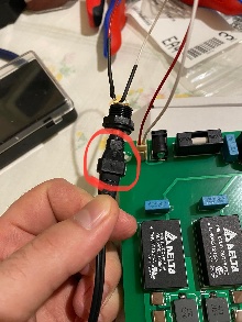
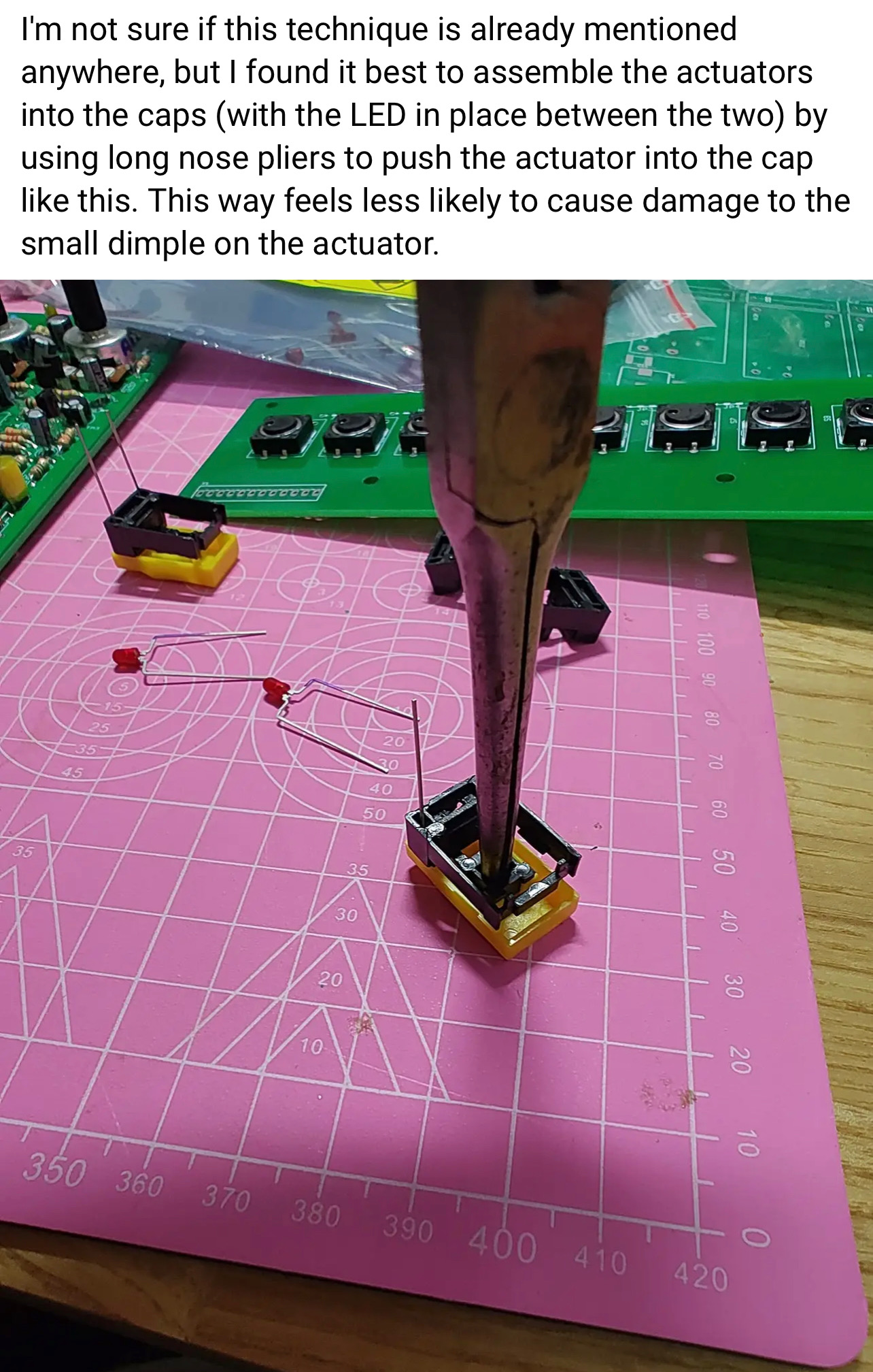
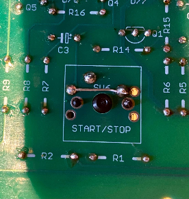
| 3 | Tactiles /caps install | heres a tip about the installation of the tactile caps:
| 01/2022 | |
| 4 | MIDI WIRING |
| 11/2022 | |
| 5 | Silkscreen wrong |
| 11/2022 | |
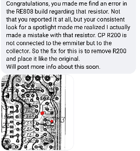
| 6 | Mainboard resistors - handclap |
in case you have the trimmer on solder side (recommended) | 11/2022 | |
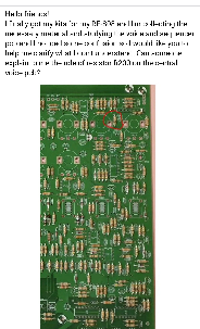
| 7 | guide /tip | for the voice board: first install all 1/8watt resistors on bottom of the pcb R1-9 are 1/8w or the switchboard do not fit use MLCC caps there and no IC socket. for IC1. when you have a solder frame: install the flat Trannys and ic sockets before you install the other parts for mainboard use for the noise transistor and muting trannys - ic socket pins to swap/change the trannys install good trimmers from nearside instead cheap trimmers from component side - better calibration possible | 11/2022 | |
| 8 | Transistors - sequencer failure | use sockets for the muting transistors. some users reported issues in combination with the pixie CPU, boot/start problems. the muting Transistors affect this - you can remove this. | 1.Dec.2022 | |
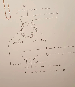
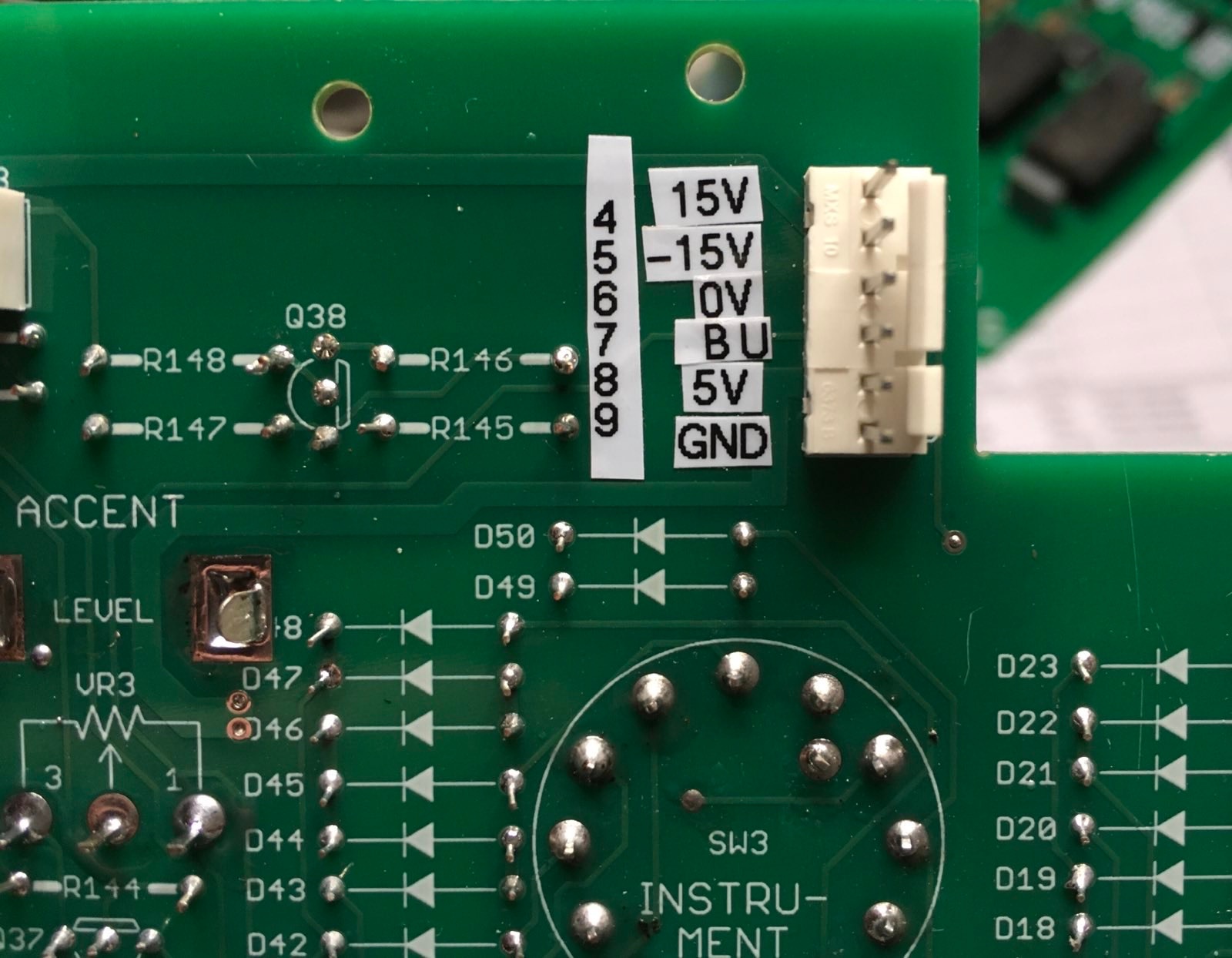
| 9 | Power Pinout |
credits by Martin.J.K - Thank you | 02.Jan.2023 | |
| 10 | general | install good trimmers on back side (solder side) - for easier calibration install the BA662 clone on solder side - in this was you can use a socket install the muting JFETS and noise Transitor on solder side for easier swapping install R333 on solder side to give you the opportunity to replace this with a trimmer (50k) to change the handclap sound.. | 02.Jan.2023 | |
| 11 | bugfix | install a jumper as shown to get your 808 working as designed
| 03. Jan.2023 | |
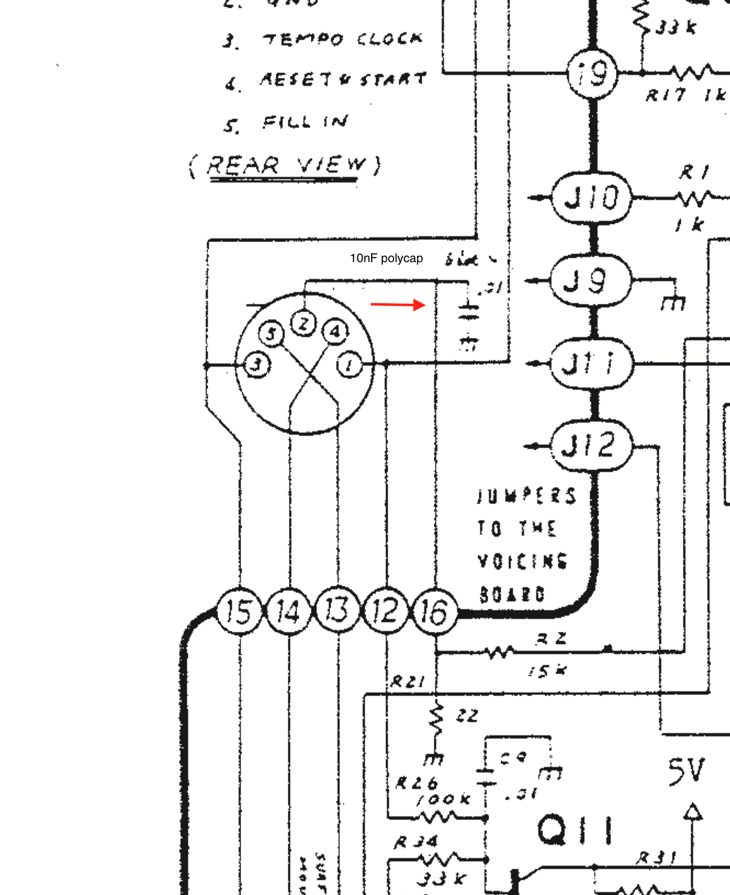
| 12 | capacitor on Sync jack | install a 10nF polyester cap or bipolar electrolyte cap at the sync jack or on the pcb
| ||
| 13 | clock calibration fix | remove C203 on mainboard (39nF) or your clock can't be calibrated in case you can't reach 120hz by trimmer end, install a 2M2 resistor in parallel on R43 | 04.Jan.2023 | |
| 14 | calibration |
| ||
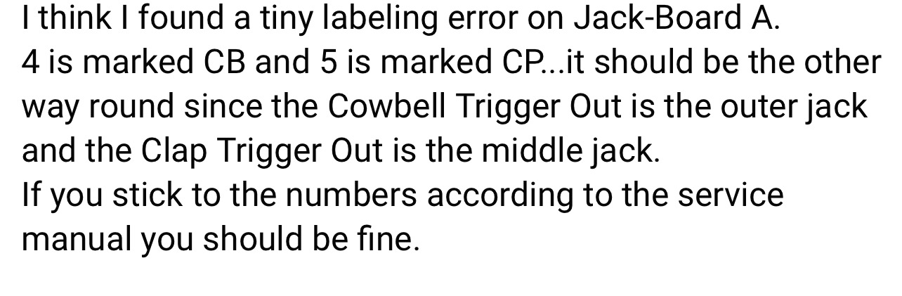
| 15 | wiring | some help.. found on FB
| ||
| 16 | calibration | change R376 to a 100K trimmer to adjust the clap reverb | ||
| 17 | MIDI connection MOD | the 3D printed part is available in my shop https://www.diysynth.de/spezial-re-808-parts/re-808-midi-anschluss-3d-druck.html or print it myself (Resin preferred) just use 2 screws to mount this at the typenumber plate holes at the rear and drill a small for the MIDI cables.
| ||
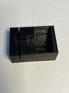
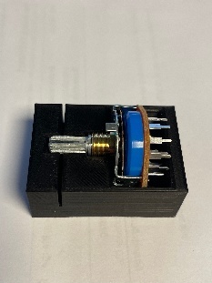
| 18 | 3D Print tool rotary switch | this tool make things easier. just drop the rotary switch inside and its easy to saw the switch to the exact given length available in my shop : https://www.diysynth.de/spezial-re-808-parts/re808-schaltersaegehilfe-3druck-teil.html
| ||
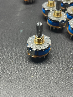
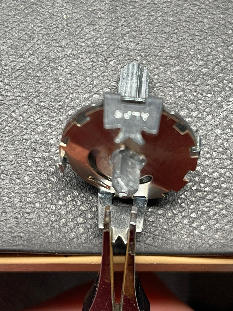
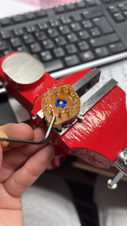
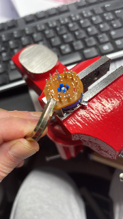
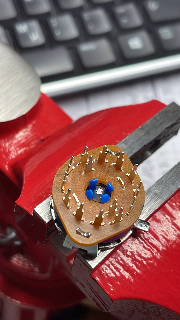
| 19 | Tip Rotary Switches | for much easier rotary switch assembling, use this knowledge PLUS the ALPS assembly guide, my infos are a additional tip how to remove and bend the tabs. Background: we dont need the upper part of the D shaft switches and we don't need the lower part of the knurled switches. for the D shaft switches you can bend the tabs at the bottom for removal as close you can - because we dont need the upper part - put the upper part (metal) in the trash bin.
for the knurled switches you can cut the pcb on bottom to remove the bottom part without bending the tabs, after you have removed the pcb - you can much easier bend the tabs !!!
after you proceed the other steps as described in the guide , you have to bend back the pins which hold the bottom part and upper part. I used here 2 tools and a hammer. in first step I punched with the smaller hex. and the hammer and later with the bigger hex. and a hammer.
|